10
3.3.2 Connection and preliminary tests
First install cable glands, then connect wires on the terminal blocks.
How to install cable glands
For each cable entry used
1. Remove plug from the cable entry with 19mm (M16 entry)
or 23mm (M20 entry) open-end
wrench.
2. Separate sealing nut from its
cable gland.
3. Screw and tighten cable gland
in the cable entry.
4. Thread the sealing nut on the
cable and pass the cable
through the cable gland.
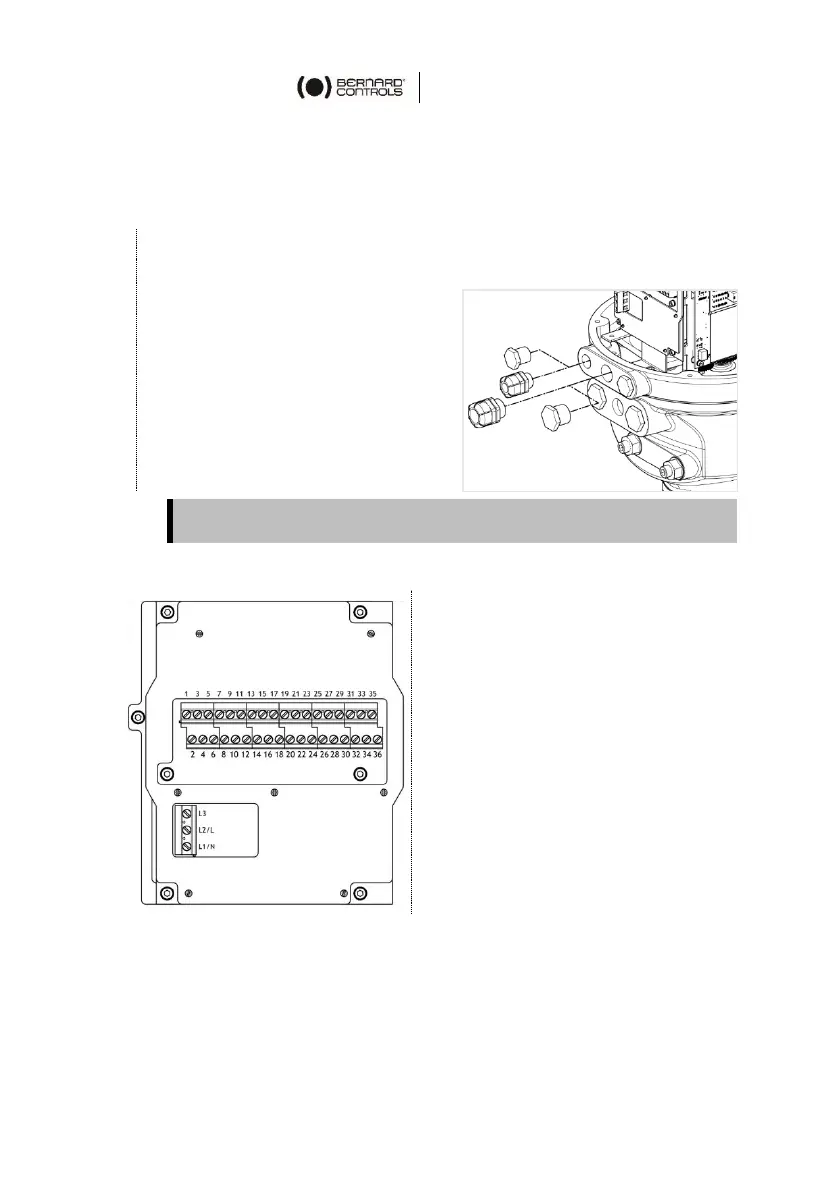
Terminal blocks
Terminal blocks are located on a
side of the electronic assembly
and consist of screw-type
terminals. There are 2 main
blocks: 1
st
is to connect power
supply, 2
nd
to connect command
and signaling.
Control terminals are 1-35 & 2-36
Power terminals (3Ph/1Ph)
3Ph: L1, L2, L3 with phase
discriminator
1Ph: L (Live), N (Neutral)
Both thermal protector and torque limit device must be integrated
into your control system in order to prevent potential damage to the
actuator or valve.
Unused entries must be kept closed by their plug.
 Loading...