11
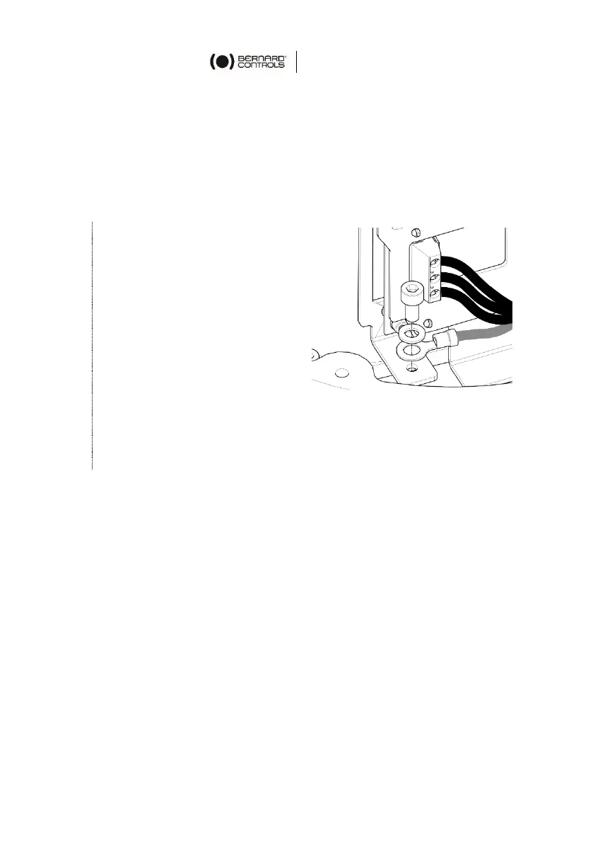
Internal ground terminal
The ground terminal is a metal tab with a fixation hole located under
the terminal board at its bottom left (see following picture).
How to wire actuator
The wiring must be done according to the wiring diagram of your
actuator.
Using a 3×0.5mm flat blade
screwdriver and a 4 mm Allen
key
5. Connect power supply on
terminals marked L1, L2 &
L3 (3Ph) or L, N (1Ph)
according to your supply
type
6. At the same time, connect
ground cable on ground
terminal.
7. Connect control and signaling wires on uneven (marked 1 to
35) and even (marked 2 to 36) upper terminals.
8. Tighten sealing nut on the cable gland when you have
completed wiring.
 Loading...