42
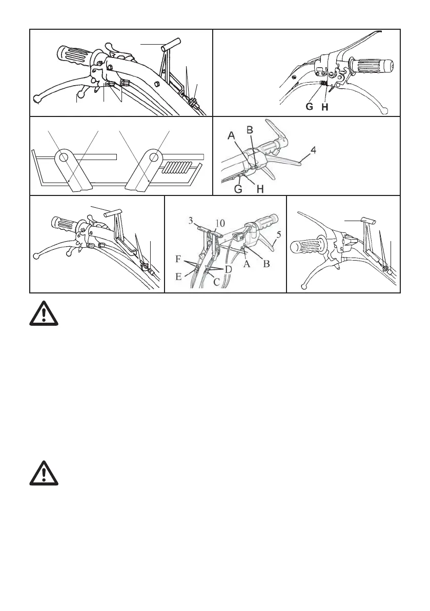
CONTROLS ADJUSTMENT
BRAKES (141)
The wheels must be locked when levers 4 and
5 (Fig. 14 - 15A - 16A) are engaged. If this is not
the case, loosen nuts B and then set adjuster A.
When adjustment is obtained lock nuts B again.
REVERSING GEAR CONTROL LEVER
(Fig. 14 - 16A e 14/1)
Check that the reversing gear lever on the
gearbox strikes against the plate as shown in
reference A, in forward speed and against plate
in reference B in reverse speed.
Use adjuster C and nuts D to adjust stroke.
ATTENTION: An incorrect position of
references A and B could CAUSE
DAMAGE TO THE GEARBOX.
CLUTCH
Check the idle stroke of the clutch lever regularly.
This should be approximately 5mm.
In order to change adjustment, loosen nut H
(Fig. 15 - 15A).
Screw or unscrew adjuster G until stroke is
approx. 5 mm, then lock nut H again.
DIFFERENTIAL LOCK (141)
If the differential lock is still engaged when
lever 3 (Fig. 16 - 16A) has been put in idle,
obtain proper adjustment by using adjuster E
and nuts F.
QUICKFIT SHUTTER
LOCK/UNLOCK LEVER
If by pulling lever 11 (Fig. 17), the implement
is not released, then set adjuster L and nuts I.
AIRBORNE NOISE
Acoustic pressure recorded at 1,6 m off the
ground in the centre of the handlebars by a B
& K 2230 instrument facing the engine.
Maximum level of acoustic pressure statistically
weighted equivalent:
90.7 dB (A)
Sound Power: 104.6 dB (A)
HANDLEBAR VIBRATION
Statistically weighed measurement in
accordance with ISO 5349: 16,2 m/sŸ2
Data refers to maximum values recorded with
the range of engines available.
Fig. 16
A
Fig. 14
54
B
10
C
D
Fig. 14/1
Fig. 15
A
B
3
E
F
Fig. 15/A
141M
Fig. 16/A
Fig. 17
11
L
I
141M
 Loading...