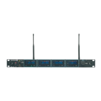
TG 1000 – Antenna Splitter
27
2.12.3 Mounting and Installation
• For the installation into a 19" rack the WA-AS 6 antenna splitter is provided with 19" holes on the left and right hand side.
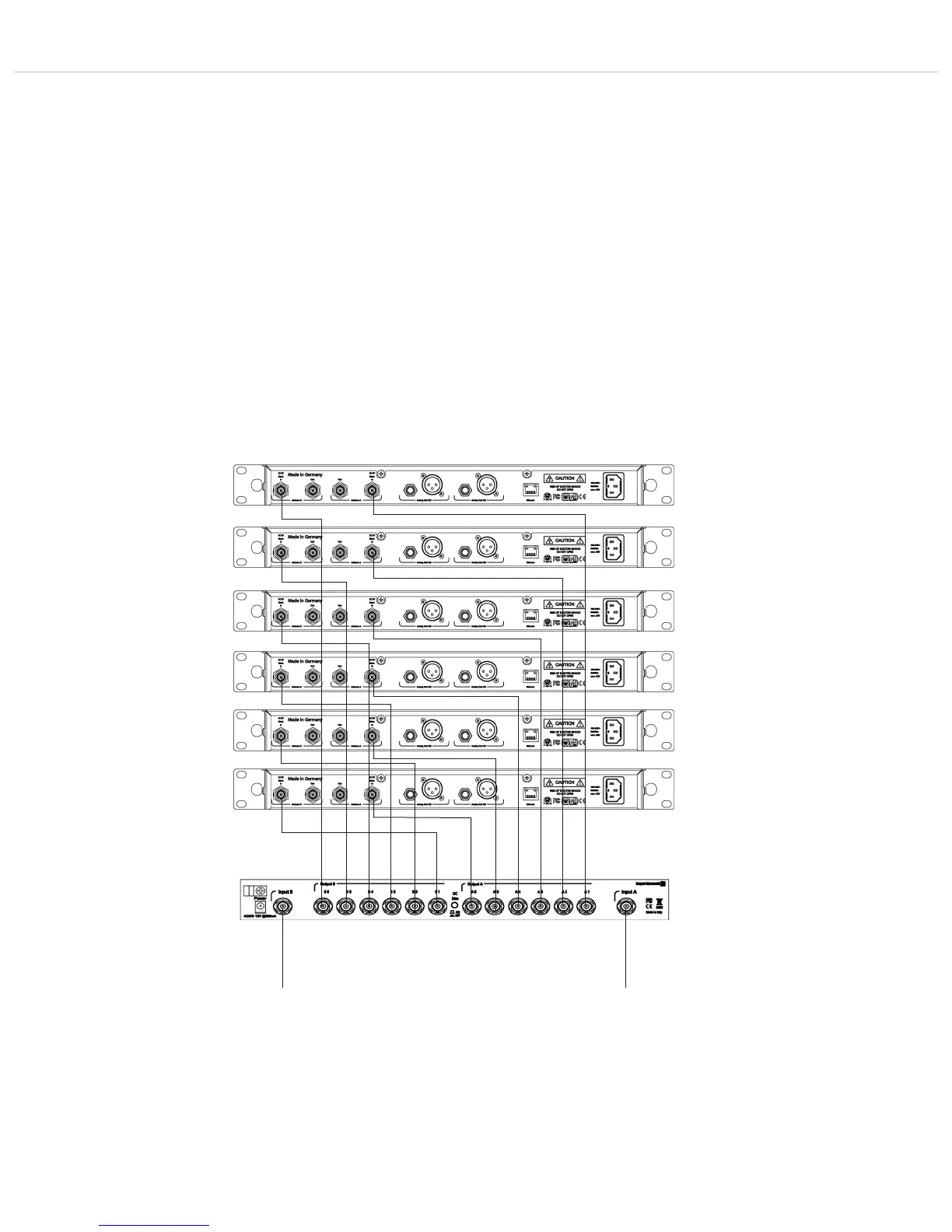
• Connect the WA-ATDA directional antenna or the WA-ATO omnidirectional antenna to the antenna inputs A and B .
• The antenna outputs of the antenna splitter are connected to the antenna inputs of the receivers by using BNC patch cables (WA-CKL). In order
to ensure the diversity operation, each receiver must be supplied with an A and B antenna signal!
• Connect the supplied power supply unit to an appropriate power outlet and the DC connection . The antenna splitter has not separate
on-off switch and is ready for operation when connected to the mains. The power on LED will illuminate.
• When using WA-AMP antenna amplifiers use the on-off button on the rear of the antenna splitter. The status LED will illuminate.
Caution: When the on-off button is pressed, the DC supply is turned off.
Important notes
• The antenna connections have a DC voltage of 8V DC. In order to avoid a short circuit, they should not touch the housing of the rack.
• Use the WA-AC antenna cable from beyerdynamic. The longer the cable, the higher the attenuation of the high frequency signal.
• For the connection of remote antennae use the WA-AC antenna cable from beyerdynamic. The longer the cable, the higher the RF signal loss.
• The connected antennae and the antenna splitter must have the same frequency range of 470 – 790 MHz.
• By cascading several TG 1000 diversity receivers you can create larger multi-channel systems by using the antenna splitter.
First receiver
Second receiver
Third receiver
Fourth receiver
Fifth receiver
Sixth receiver
Connection of WA-ATDA
directional antenna
or
WA-ATO omnidirectional antenna
Connection of WA-ATDA
directional antenna
or
WA-ATO omnidirectional antenna