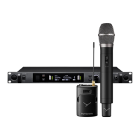
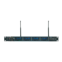
TG 1000 – Digital Diversity Receiver
6
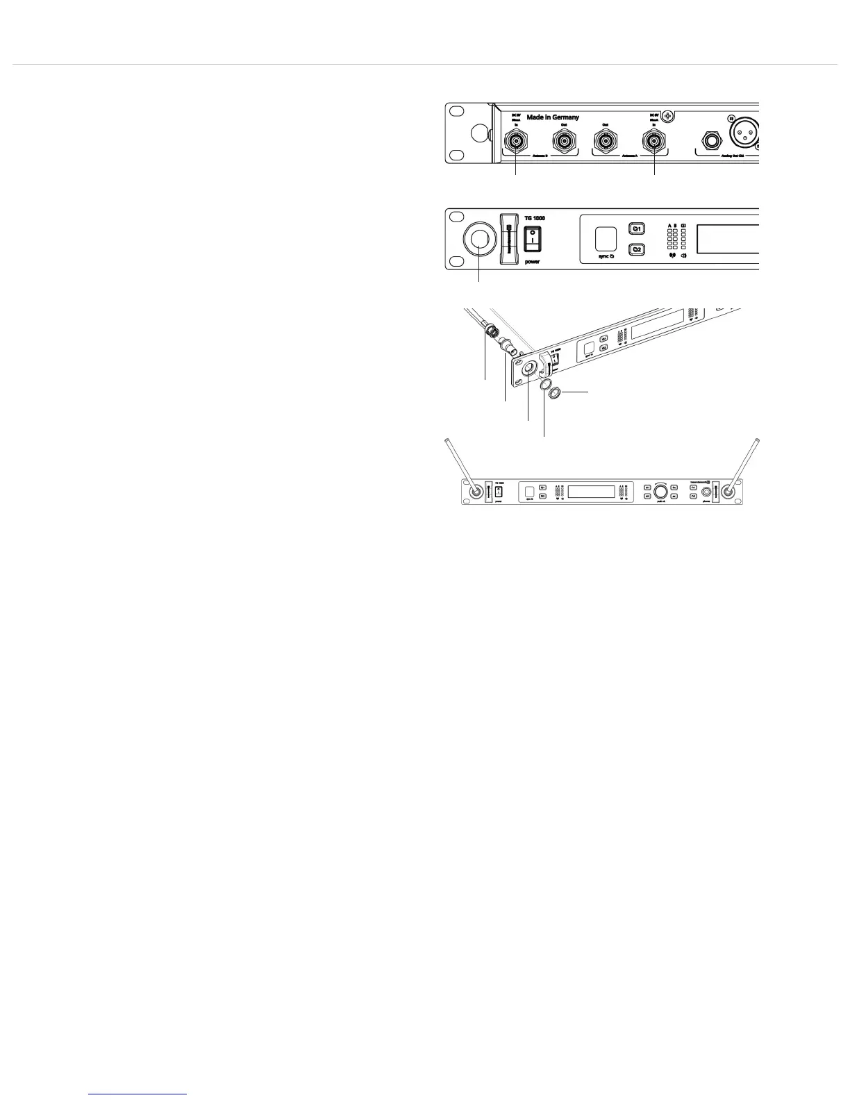
2.3 How to Connect the Antennae
• Connect the supplied antennae to the A and B antenna inputs
and set them at an angle (approx. 60°) in the shape of a “V”.
Important: For the diversity operation it is absolutely necessary
to connect both antennae! A weighting circuit ensures that an
antenna is selected that supplies the better signal.
• As an alternative, you can mount the antennae on the front of the
receiver. Please use the WA-CKF antenna front mounting kit.
• Connect the antenna cable of the antenna front mounting kit to
the A and B antenna inputs .
• Remove the protective caps from the holes for mounting the
antennae on the front .
• Remove the nuts and washers of the supplied adapters.
• Slide the adapters through the appropriate hole with the thread
of the adapter showing to the front.
• Tighten the adapters with the washers and the nuts.
• If required, mount the receiver into a 19" rack.
• Connect the antenna cables to the rear of the adapter.
• Connect the antennae to the front (BNC sockets) of the adapter.
• Set the antennae at an angle in the shape of a “V”.
2.4 How to Connect and Install
Remote Antennae
If the reception is not good, we recommend using remote antennae.
We recommend the passive WA-ATDA directional antenna (optional
available). In order to power active antennae, the receiver provides
a short-circuit-proof voltage of 8 V DC at both antenna inputs with
a maximum load of 75 mA.
1. Connect the receiving antennae to the corresponding antenna
inputs and place the antennae to the right and left of the
receiver in the operating range where the transmitter is to be
used. If necessary change the position of the antennae to
improve diversity reception.
2. The distance between the two receiving antennae should be at
least 1 m.
3. The distance between transmitting and receiving antennae
should be at least 3 m to avoid overloading and interference
between different channels. We therefore recommend installing
the antennae in a high position, especially in multi-channel
systems.
4. If the operating range of the transmitters is greater than the
stage, the antennae can be mounted vertically on the ceiling.
The distance between the two receiving antennae should be
approximately half the total operating range.
Important:
1. Install the receiving antennae in the same area as the transmitter.
2. To avoid interference do not install the antennae near digitally
controlled components.
3. Keep a minimum distance of 0.5 m from metallic objects,
including reinforced concrete walls or pillars.
4. Do not bend the antenna cables at the antenna input, and
ensure that they are not subjected to undue stress.
Antenna
cable
Adapter
Nut
Washer