9
50 800 315 698 M36 24 10 32 430 240 56 264,8
60 840 315 698 M36 24 10 32 430 240 56 264,8
Installation, Operation and Maintenance Manual
MAN616_EAC Rev. 5 July 2020
Section 2: Installation
Installation
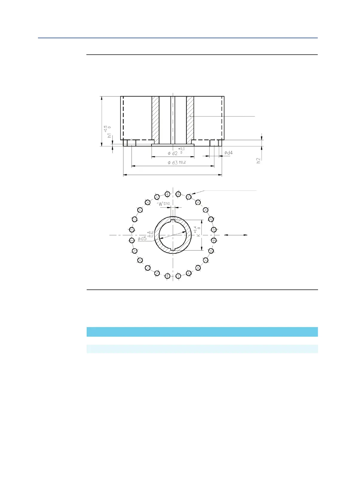
Drive sleeve
H max
N.16 holes ange N.12 holes ange
N. THREADED HOLES
Flange sizing according to ISO
ø d1 max
Flow line
Top view of the scotch yoke mechanism
(actuator shown in closed position)
Models 50, 60
Figure 4 Coupling Dimensions for Scotch Yoke Standard Actuators
Dimensions in millimeters
Actuator model Ø d
1
Ø d
2
Ø d
3
Ø d
4
N h
1
h
2
H max Ø d
5
W K
Table 4. Size Table