8
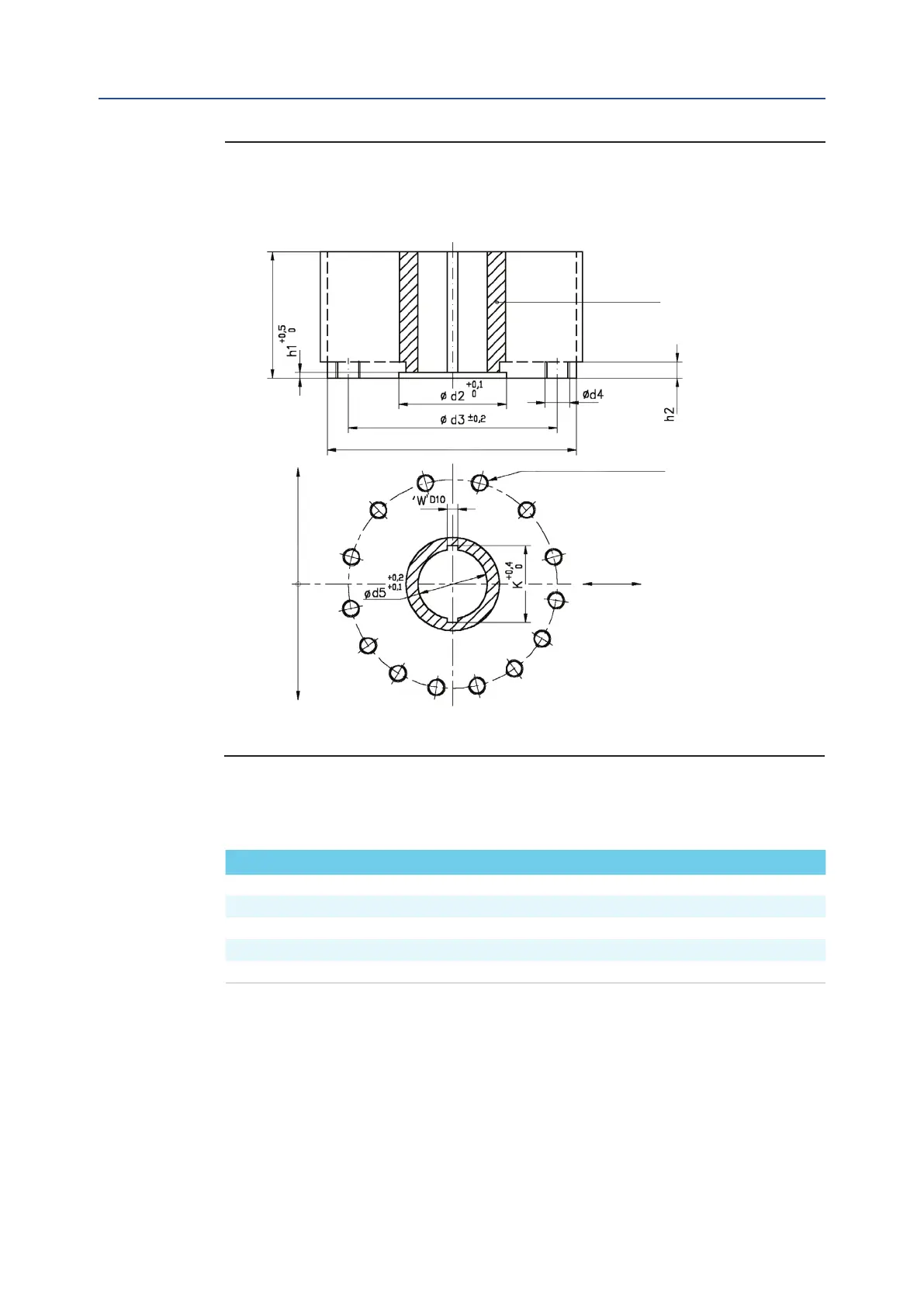
14 580 250 483 M36 12 10 29 340 175 45 195,8
18 680 290 603 M36 16 12 32 350 200 45 220,8
32 780 290 603 M36 16 12 32 400 220 50 242,8
35 780 315 603 M36 16 11 32 400 240 50 242,8
42 840 310 603 M36 16 12 32 400 220 50 242,8
July 2020
Installation, Operation and Maintenance Manual
MAN616_EAC Rev. 5
Section 2: Installation
Installation
Drive sleeve
H max
N.16 holes ange N.12 holes ange
N. THREADED HOLES
P.C.D., number and size
according to ISO 5211
ø d1 max
Flow line
Top view of the scotch yoke mechanism
(actuator shown in closed position)
Models 14, 18, 32, 35, 42
Figure 3 Coupling Dimensions for Scotch Yoke Standard Actuators
Dimensions in millimeters
Actuator model Ø d
1
Ø d
2
Ø d
3
Ø d
4
N h
1
h
2
H max Ø d
5
W K
Table 3.