IX. MAINTENANCE AND SERVICE- cont.
60
6060
60
10. Leave the unit like this until the battery is expended and the unit turns itself off.
11. Plug the Bio-Med Devices external power supply into the side of the unit. This plug and jack are
keyed so the red dot on the plug must be facing the front of the unit in order for them to engage.
Power on the unit by first turning the ON/OFF switch to OFF and then back to ON.
12. Press the SETUP key and then the CAL MENU key.
13. Press BATTERY, press CONTINUE and enter the authorization code.
14. Press the key labeled RESET. This will change to green indicating the gauge has been zeroed.
15. Turn the unit off and allow it to charge the battery fully. This may take up to five hours.
16. When the Charging LED stops blinking, the battery will be fully charged. Unplug the external
power supply, turn on the unit and verify the battery gauge indicates a full battery.
NOTE: If RESET changes to red when pressed, there has been an error. Press the key again. If it is
continually red, then there is a problem with the battery gauge chip, IC202, or communication between this
chip and the microprocessor.
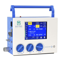
3. FRONT BEZEL
3. FRONT BEZEL3. FRONT BEZEL
3. FRONT BEZEL
1. Remove the rear panel.
2. Disconnect and remove the battery or, in lieu of removal, the battery may be held in place with tape.
3. Place the Crossvent on its back with the bezel facing up.
4. While holding down on the case, pull up on the edges of the bezel, first one side and then the other,
working from one side to the other until it is free. The knobs that are pressed onto the valve shaft
extenders cause the resistance to removal. The knobs will come off with the bezel as it is removed.
Be aware that the RFI gaskets may come off as the bezel is removed. Retain them for reinstallation.
5. To re-install, make sure the RFI conductive gaskets are in place on the outside edges of the bezel as
well as around the display window. Also be sure the amplifying tube for the beeper on the PCB is
positioned properly behind the alarm holes in the front of the bezel. Then place the bezel over the
valve shaft extenders and fit it into the case.
6. Press the knobs back on the extenders, turn the unit over and proceed in reverse order as before.
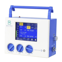
4. DISPLAY/TOUCHSCREEN
4. DISPLAY/TOUCHSCREEN4. DISPLAY/TOUCHSCREEN
4. DISPLAY/TOUCHSCREEN
Warning: High voltage is present at the backlight connector (JBL) when the power
is on.
1. Remove rear panel.
2. Disconnect and remove the battery or, in lieu of removal, the battery may be held in place with tape.
3. Remove the Bezel.
4. The display/touchscreen is connected to the PCB on the left side with two ribbon cables (some may
have one), on the right side with one connector to the backlight, and underneath by one ribbon
cable. Unplug the display/touchscreen on its left side where it connects to the PCB and separate
the backlight plug on the right side. Leave the ribbon cable underneath to the display plugged into
the PCB at this point.
5. There are two clamps diagonally opposed to one another on the standoffs for the display.
Disengage these.
6. Carefully lift the display/touchscreen assembly straight up and away from the PCB just until it
separates from the PCB.
7. With the display separated from the PCB, tilt it slightly by lifting the right side and unplug the
ribbon cable from the PCB.
8. Re-install in reverse order.
9. If this is a new assembly, then refer to the Touchscreen calibration procedure in Part A-2 of this
section to calibrate the touchscreen once the unit is back together.
5. POPULATED CIRCUIT BOARD (PCB)
5. POPULATED CIRCUIT BOARD (PCB)5. POPULATED CIRCUIT BOARD (PCB)
5. POPULATED CIRCUIT BOARD (PCB)
See Cautions at the beginning of this section.
1. Set the MAX Pressure and PEEP knobs fully off (CCW).
2. Remove the rear panel, battery and front bezel.
3. From the rear of the unit, unplug the tubes from the transducer(s).
4. Unplug the cable from the solenoid board to the PCB.
5. Unplug the pressure sensor switch and remove the two nuts that secure it to the battery enclosure.
Taking care not to damage or kink the tube on the pressure switch, remove the switch from the
threaded studs and hold it off to the side in order to unplug the Flow Sensor connector
(JPNEUMO) underneath it.
6. Once the Flow Sensor is unplugged, secure the pressure switch back in place. There is no need to
tighten the nuts at this time as they will have to be removed for reinstallation of the PCB later.
7. Unplug the cable from the RS232 board to the PCB.