EasyManuals Logo

BIXOLON SRP-270 Service Manual

BIXOLON SRP-270
85 pages
To Next Page IconTo Next Page
To Previous Page IconTo Previous Page
Page #38 background imageLoading...
Page #38 background image
Rev. 3.02
- 38 -
SRP-270
4-3-9 DIP Switch Circuit
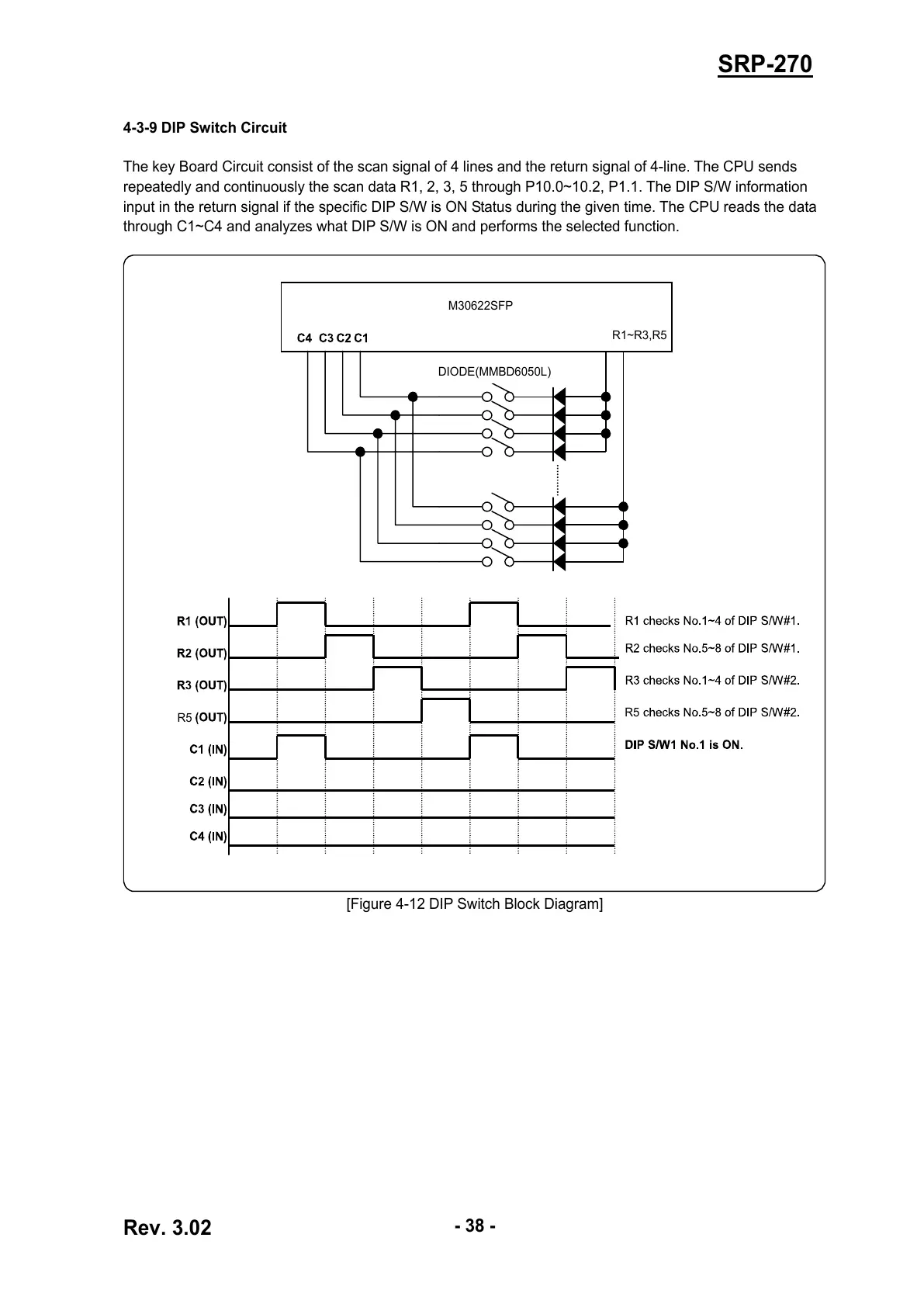
The key Board Circuit consist of the scan signal of 4 lines and the return signal of 4-line. The CPU sends
repeatedly and continuously the scan data R1, 2, 3, 5 through P10.0~10.2, P1.1. The DIP S/W information
input in the return signal if the specific DIP S/W is ON Status during the given time. The CPU reads the data
through C1~C4 and analyzes what DIP S/W is ON and performs the selected function.
[Figure 4-12 DIP Switch Block Diagram]
M30622SFP
R1~R3,R5
DIODE(MMBD6050L)
R5
R5
All manuals and user guides at all-guides.com

Table of Contents

Other manuals for BIXOLON SRP-270

Questions and Answers:

Question and Answer IconNeed help?

Do you have a question about the BIXOLON SRP-270 and is the answer not in the manual?

BIXOLON SRP-270 Specifications

General IconGeneral
ColorNo
Maximum print size-
Media thickness76 mm
Print technologyDot matrix
Power requirements120-230VAC
Standard interfacesParallel, Serial

Related product manuals