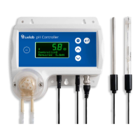
Multiple sensors/switches may be used in both circuits: in parallel with the NO
circuit, and in series, with the NC circuit.
A cable sensing circuit is used to detect that the Alarm and Lockout cable is fitted.
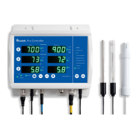
The normally open circuit is
between the White and Yellow
wires. An example circuit is shown
to the right.
Note: to enable the lockout
functionality, the Green and Yellow
wires must be connected.
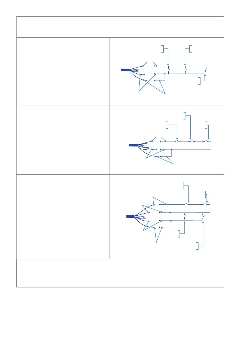
The normally closed circuit is
between the Brown and Yellow
wires. An example circuit is shown
to the right.
Note: to enable the lockout
functionality, the Green and Yellow
wires must be connected.
A combination of the above two
circuits is also possible using the
Brown, White and Yellow wires as
shown to the right.
Note: to enable the lockout
functionality, the Green and Yellow
wires must be connected.
The choice of circuit used will be determined by the specific external sensor that is
used.
Refer to the Sensor Manufacturer’s documentation for more information
NO
switch 3
NO
switch 1
NO
switch 2
Yellow wire
Green wire
White wire
NC
switch 1
NC
switch 2
NC
switch 3
Yellow wire
Green wire
Brown wire
NC
switch 1
NC
switch 2
White wire
Green wire
Yellow wire
Brown wire
NO
switch 3
NO
switch 4