4.0 Alarms & External Lockouts
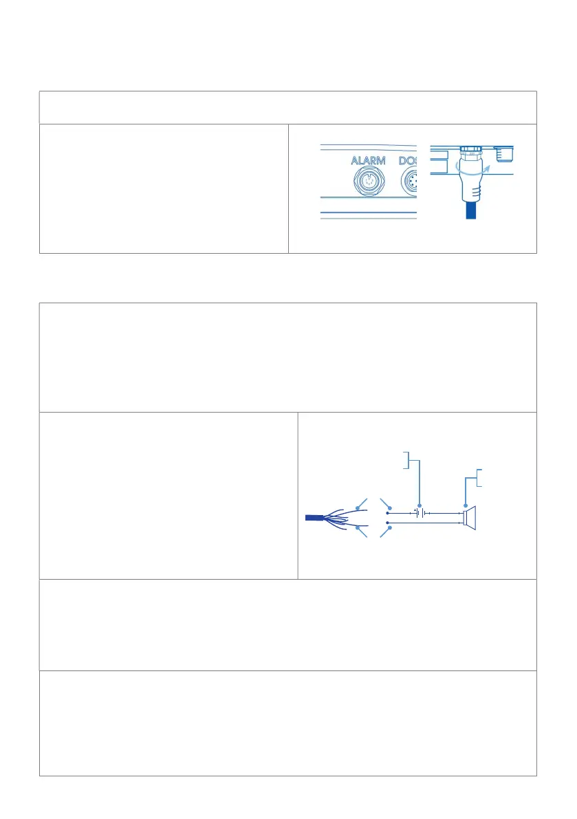
4.1 Connecting alarm & external lockout cable
using the alarm & external lockout cable supplied
with the receptacle on the Bluelab
Pro Controller labelled ‘ALARM’.
Push and screw the collar fully into
the receptacle.
2. Connect the other end of the cable
to an external alarm device. Refer to
section 4.2 for functionality details.
4.2 Alarm & lockout cable functionality
The Bluelab Pro Controller is supplied with an alarm and external lockout
cable. It has two purposes:
1. It enables an external alarm to be fitted to the Bluelab Pro Controller, such as a
light or horn. This could be useful in a larger growing area, for example, where
the controller is housed in a pump room, and not easily viewed.
2. It enables external devices such as flow switches and float switches to be used,
so that external conditions can interrupt dosing.
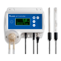
External alarm connection
The controller closes a (normally open)
electronic relay contact when in an alarm
condition. This relay contact can be used
as a switch to allow the function of an
external alarm.
The internal relay operates between the
Grey and Pink wires of the Alarm &
Lockout cable. An example circuit is
shown to the right.
The maximum voltage that the internal relay can be used to switch is 24VAC
or DC with a maximum current of 250mA. These ratings must not be exceeded. If
higher voltages or currents are to be switched, then an external relay, rated
correctly for the desired device, must be used, driven by the internal relay.
Any connections to mains power or mains powered devices must be made by an
appropriately qualified electrician.
dosing lockout connection
The Bluelab Pro Controller can be inhibited (locked out) from dosing in response to
an external condition, such as a pump being switched off or having failed, or a float
switch indicating a level is above or below a particular level.
There are two lockout circuits available: a normally open circuit (NO) which will
inhibit the Bluelab Pro Controller when a contact is closed, or a normally closed
circuit (NC) which will inhibit the Bluelab Pro Controller if a contact is opened.
Alarm or
Sounder
Power
source
Pink wire
Grey wire