JUST POWER ON 97
3.8.3 Link Port 1 & 2 Interface Link Port 1、2
3.8.4 COM-Electricity Meter Communication Interface
For electricity meter communication:
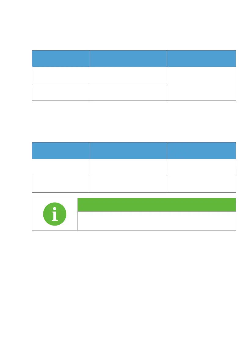
Descriptions
For details of the meter connection, please refer to the meter
manual.
Table 3-6
Table 3-7 Interface Description
Operation steps.
Step 1 : Remove the unconnected end of the COM connector adapter counter-
clockwise.
Step 2 : Thread the extension cable into the connector shell and install the
corresponding signal cable into the connector pins.
Step 3 : Tighten the screws of the connector with a screwdriver.
Step 4 : Gently pull the connection cable of 2 pins to determine whether the
connection is tight;
Step 5 : Tighten the connector shell and nut clockwise.
Interface Interface function Remark
Link Port 1 Connect the IOT controller
Connect the battery packLink Port 2
For details, please refer to
6.1 complete machine
connection
485 electricity meter
communication port
Interface function Wiring method
A(1)
B(1)
A: RS485 differential signal +
B: RS485 differential signal -
Connect meter A2
Connect meter B2