11 BA-106/1EA M53.10XX
2 - Machine setup
2.2 - Connecting to compressed air system
2.3 - Electrical connection
ATTENTION:
A quick disconnect must be inserted in the air line supply a max. 6 feet
(1.8 meters) from the machine.
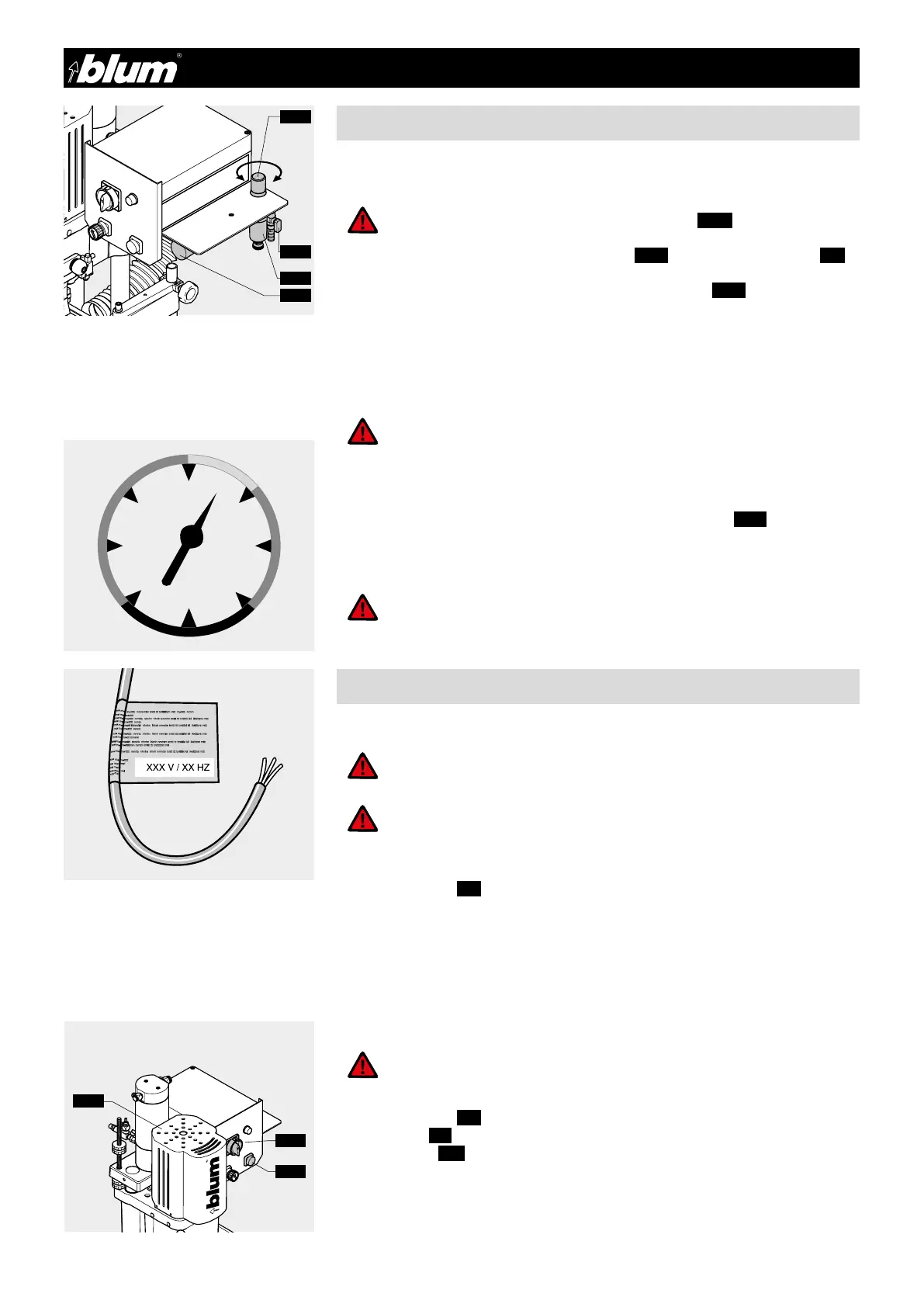
2.2.2) Setting operating pressure
• Set operating pressure set 90 psi using pressure adjusting knob (2.11)
(Pmin= 80 psi)
(Pmax= 100 psi)
2.3.1) Electrical connection
ATTENTION:
The electrical connection must be performed by a qualied electrician!
• Set power switch (3.1) to OFF
• Mount a plug conforming to DIN, VDE, IEC or UL requirements, or hardwire machine
directly to the supply circuit.
• Provide for circuit breaker of 15 A (see Chapter 10 - Diagrams).
ATTENTION:
The machine is designed for the voltage printed on the label of the con-
nection cable. Incorrect voltage may result in equipment damage
or personal injury or both.
2.3.2) Checking motor rotation
ATTENTION:
During the following procedure, keep your hands away from the work
area of the machine
• Set power switch (3.1) to ON
• Briefly press (3.2) drill/press stroke switch
• The motor fan (2.9) must turn in the direction of the arrow
ATTENTION:
Do not set the regulated air pressure above 100 psi. Higher pressure
may result in equipment damage or personal injury or both.
ATTENTION:
During the following procedure, the boring unit (4.23)
makes an upward motion
2.2.1) Connecting air supply
• Connect the air supply to the system vent valve (2.12) on the air filter assembly (7.1)
This valve is used to vent air pressure from the air control system. Note that the air
pressure remains in the cylinder when the system vent valve (2.12) is in the vent posi-
tion (see section 7.4 for cylinder venting instructions).
• Slide 3/8” rubber ID hose onto the barbed connector provided
• Optional adapter for 3/8” NPT male threads is available
• Open system vent valve
• This system vent valve is used to vent the air pressure from the air control system
PSI
80
100
120
140
0
20
40
60
 Loading...