21 BA-106/1EA M53.10XX
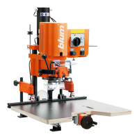
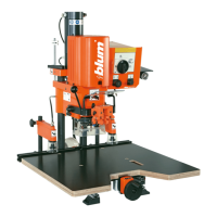
6.1 - Boring hole groups
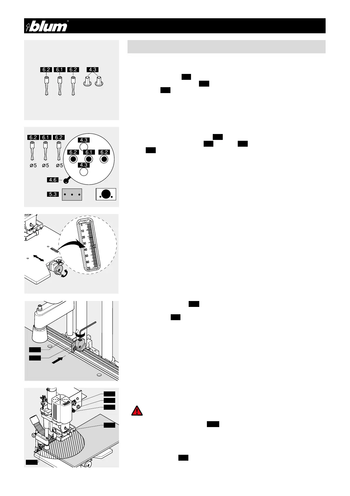
6 - Other installation
6.1.1) Required parts
• Drill bits:
1x ø 5 mm clockwise (6.1) (marked in black)
2x ø 5 mm counterclockwise (6.2) (marked in orange)
• Cover caps (4.3)
• Cabinet side
6.1.2) Setting drill bit length
(See point 4.1.2)
6.1.3) Setting boring pattern
• Pull out boring head securing knob (4.5)
• Simultaneously move the lever (4.6) to symbol (5.3) • Release boring head securing
knob (4.5)
6.1.4) Inserting drill bits into the chuck
(See point 4.1.4)
6.1.5) Checking boring depth setting
(see points 4.1.5 / 4.1.6 / 4.1.7)
6.1.6) Setting stroke speed
(see points 4.1.8 / 4.1.9 / 4.1.10)
6.1.7) Setting boring distance
• Set the desired dimension using the hand wheel
• Example: SYS - 37 mm
6.1.10) Setting clamps (optional) (4.17) to the material thickness
(See p oint 4.1.15)
6.1.11) Boring
(See p oint 4.1.18)
6.1.12) Releasing clamps (optional)
• Press clamp button (3.3)
• Push cabinet side to the next stop.
ATTENTION:
All items except for the work piece should be removed from the work
area of the machine. Keep your hands out of work area (A).
6.1.8) Setting ruler stops (2.7)
Set the ruler stops (2.7) to the desired dimension and clamp.
IMPORTANT:
Indicator edge is on the inside of the sliding part.
6.1.9) Placing cabinet side on the work table and pushing up against the stop
(See p oint 4.1.14)
!
 Loading...