19 BA-106/1EA M53.10XX
5.1 - Wing mounting plate installation
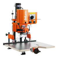
5 - Mounting plate installation
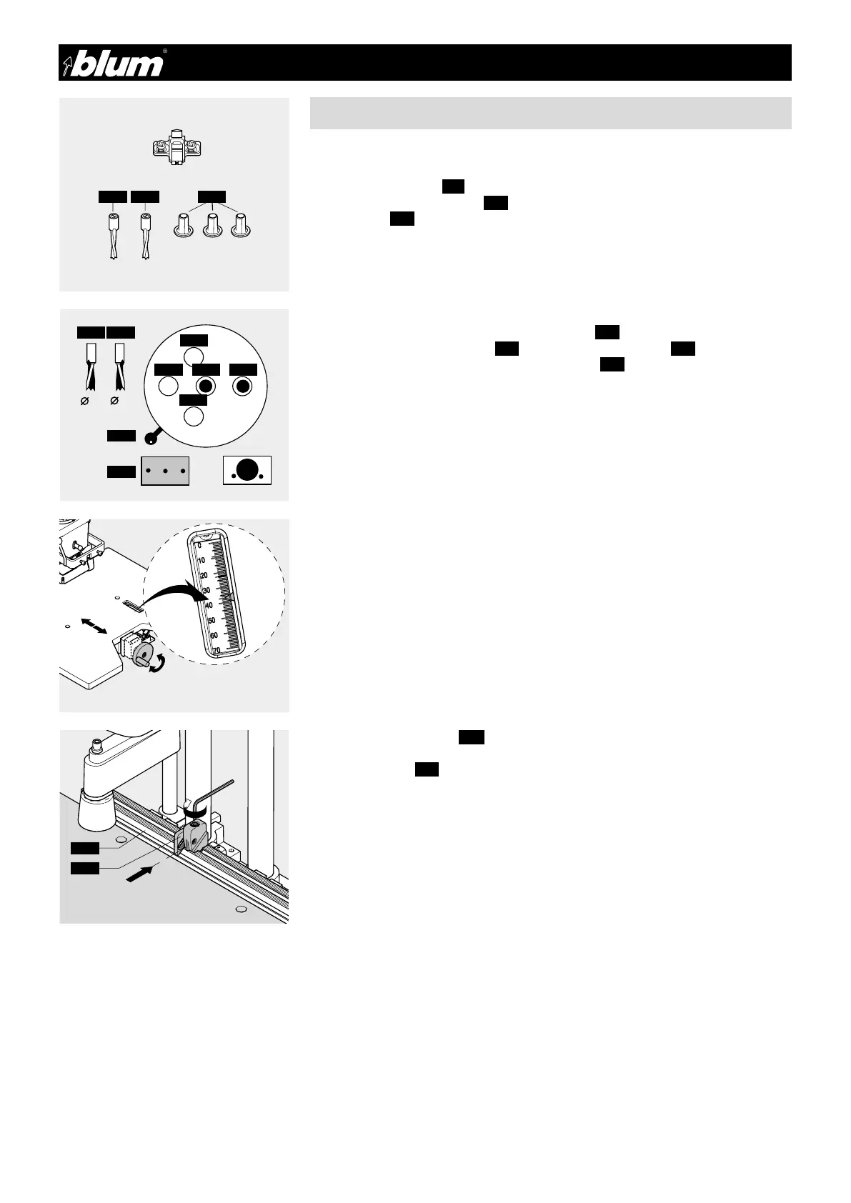
5.1.1) Required parts
• Drill bits:
1 x ø5 mm clockwise (5.1) (marked in black)
1 x ø5 mm counterclockwise (5.2) (marked in orange)
• Cover caps (4.3)
• Cabinet side
• Wing mounting plate with system screws
5.1.2) Setting drill bit length
(see point 4.1.2)
5.1.3) Setting boring pattern
• Pull out spring loaded boring head securing knob (4.5)
• Simultaneously move the lever (4.6) to the “Hole group” symbol (5.3)
• Release spring loaded boring head securing knob (4.5)
5.1.4) Installing drill bits into the chuck
(see point 4.1.4)
5.1.5) Checking boring depth setting
(see points 4.1.5 / 4.1.6 / 4.1.7)
5.1.6) Setting the stroke speed
(see points 4.1.8 / 4.1.9 / 4.1.10)
5.1.7) Setting the boring distance
• Set the desired dimension using the hand wheel
• Example: SYS-37 mm
5.1.8) Setting ruler stops (2.7)
Set the ruler stops (2.7) to the desired dimension and clamp.
IMPORTANT:
Indicator edge is on the inside of the sliding part.
!
 Loading...