14 BA-106/1EA M53.10XX
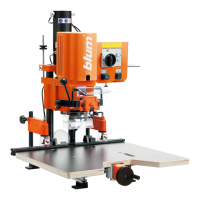
4.1 - Concealed hinge installation
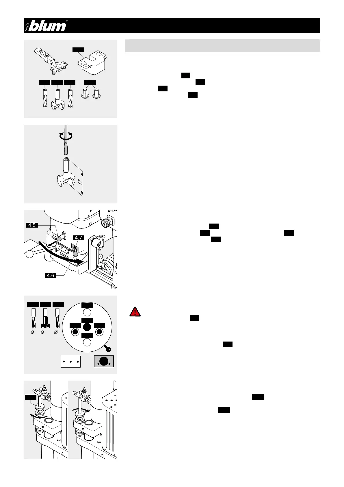
4 - Hinge installation
4.1.1) Required parts
• Bits:
1x ø 35 mm clockwise (4.1) (marked in black)
2x ø 8 mm counterclockwise (4.2) (marked in orange)
• Cover caps (4.3)
• Insertion ram MZM.00XX (4.4) (see catalogue to determine the proper insertion ram
for the respective concealed hinge)
• Dowelled hinge (press-in)
IMPORTANT:
All drill bits must be the same length
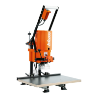
4.1.2) Setting drill bit length
• The total length of the drill bits (from bit-tip to adjustment screw)
should be 57 mm
• To correct drill bit length, adjust screw accordingly using a screwdriver
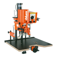
4.1.3) Setting boring pattern
• Pull out boring head securing knob (4.5)
• Simultaneously move the lever (4.6) to the “Concealed hinge” symbol (4.7)
• Release boring head securing knob (4.5)
• Push drill bits all the way into the chuck (The flat section on the drill bit shank must be
in line with the set screw)
• Use a hex wrench to tighten the set screws
• Insert cover caps into the unused chucks (4.3). This will keep the chucks clean and
prevent the set screws from shaking loose
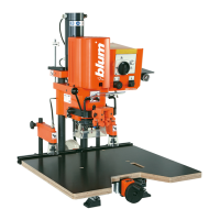
4.1.5) Setting boring depth
• Set boring depth using the bottom knurled hand wheel (4.10)
(One turn equals 1.5 mm)
• Secure the bottom knurled hand wheel (4.10) (lock)
4.1.4) Inserting drill bits
ATTENTION:
Disconnect the machine from the power suplly.
Drill power switch (3.1) to OFF
!
 Loading...