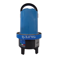
Shape: it is possible to select one of the standard shapes
(circular, rectangular, etc ...) or the customized shape that
allows you to model a non-standard channel by defining a
maximum of 32 widths at as many dimensions (see
dedicated paragraph).
Calibration level: indicates the difference, expressed in
millimeters, between the value read by the sensor and the
real level value.
This value will be added algebraically to the value read by
the sensor for the purpose of a correspondence between
the value read and that measured/verified by the operator.
You can enter a numerical value or use the calibration
window by tapping on the magic wand. The window
displays the data read by the sensor in real time. By
inserting the measured value with a rod inside the channel,
the offset value is automatically determined.
Position from the bottom: indicates the sensor installation
height, expressed in millimeters from the bottom of the
channel.
Sediment height: indicates the amount of deposit (sludge)
present in the canal, expressed in millimeters from the
bottom of the canal. The instrument uses this value for the
correct flow calculation.
Measure system: the instrument uses the international
metric system. The unit of measurement for entering a
parameter (e.g. geometry height) is always specified near
the input field.
Volume units, time units: used to determine the unit of
measurement in which the flow rate calculated by the
instrument is expressed.
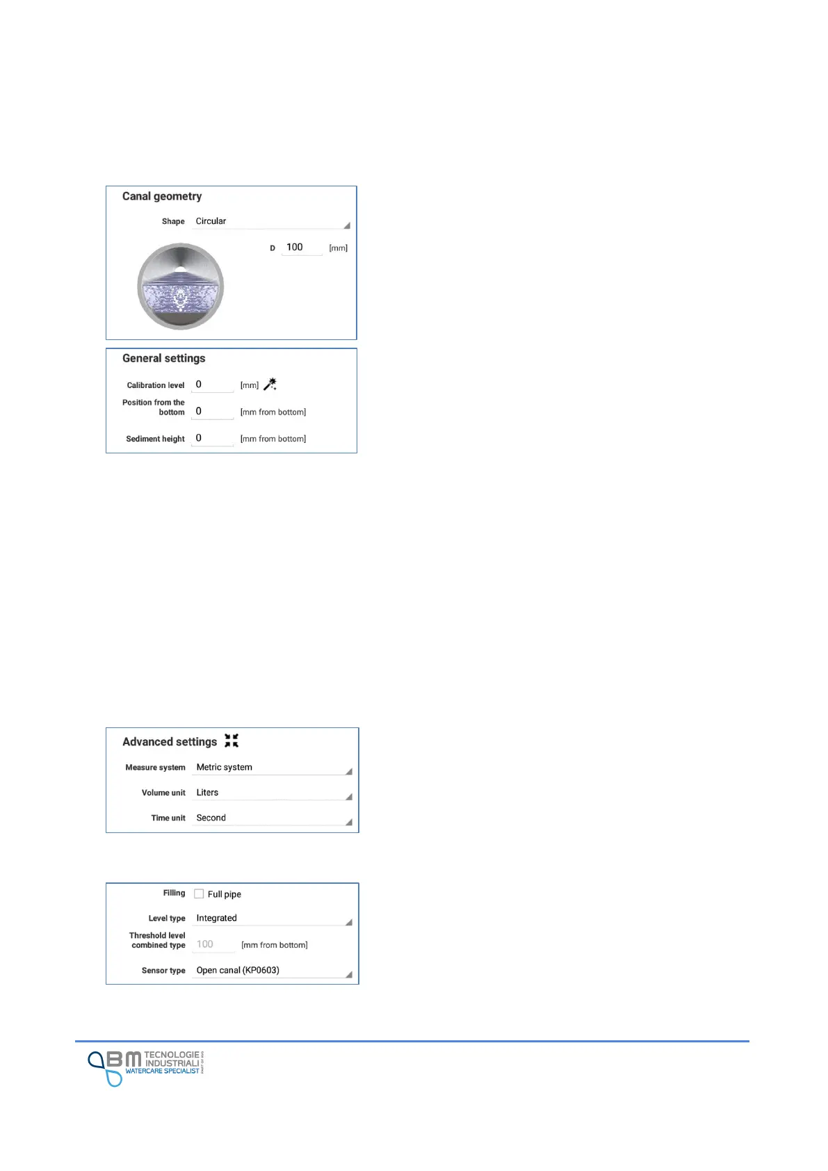
Filling: tick the “Full pipe” box in case the flow rate
calculation has to be done considering the maximum
geometry level, ignoring the one read by the sensor.
Level type: indicates how to determine the liquid level in
the channel: