13.1 Overload Ixt
The admissible load behavior depends on various technical data of the frequency
inverters and the ambient conditions.
The selected Switching frequency 400
defines the rated current and the available
overload for one second and sixty seconds, respectively. The Warning Limi
Term Ixt 405 and Warning Limit Long Term Ixt 406 are to be parameterized ac-
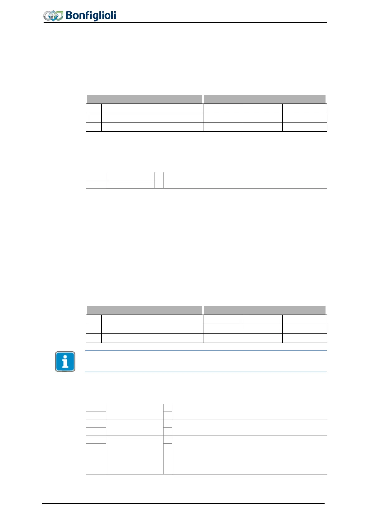
No.
Description Min. Max. Fact. sett.
405 Warning Limit Short Term Ixt 6 % 100 % 80 %
406 Warning Limit Long Term Ixt 6 % 100 % 80 %
Exceeding of warning limit is signaled by 165 - Warning Ixt”.
Digital signals indicate the attainment of warning limits.
Warning Limit Short Term Ixt 405 or Warning Limit
Long Term Ixt 406 is attained.
1)
For linking with inverter functions
13.2 Temperature
The ambient conditions and the energy dissipation at the current operating point
result in the frequency inverter heating up. In order to avoid a fault switch-
frequency inverter, the Warning Limit Heat Sink Temp.407 for the heat sink temper-
ature limit and the
Warning Limit Inside Temp. 408 as an internal tempe
are to be parameterized. The temperature value at which a warning message is out-
put is calculated from the type-dependent temperature li
warning limit.
The switch-
off limit of the frequency inverter for the maximum temperature is an
internal temperature of 65 °C and a heat sink temperature of 80 °C – 90 °C.
Warning Limit Heat Sink Temp.
Warning Limit Inside Temp.
Minimum temperatures are defined as -10 °C (interior) and 30 °C (heat sink tempera-
ture.
Digital signals indicate the attainment of warning limits.
Warning Heat Sink
Temperature
The value “80 °C minus Warning Limit Heat Sink
Temp.
407” is attained.
Warning Inside
Temperature
The value “65 °C minus Warning Limit Inside Temp.
408” is attained.
Warning Over-
temperature
− “80 °C minus Warning Limit Heat Sink Temp.
407” or
− “65 °C minus
Warning Limit Inside Temp. 408”
12 -
2)
1)
For linking with inverter functions
150 Operating Instructions ACU 06/13
 Loading...
