13.3 Controller status
The intervention of a controller can be indicated via the control unit or LED's. The
selected control methods and the matching monitoring functions prevent a switch-
of the frequency
inverter. The intervention of the function changes the operating
behavior of the application and can be displayed by the status messages with param-
eter
Controller status 275. The limit values and events which result in the interven-
tion by the corresponding controller are described in the corresponding chapters.
behavior during the intervention of a controller is configured with the parameter Con-
409.
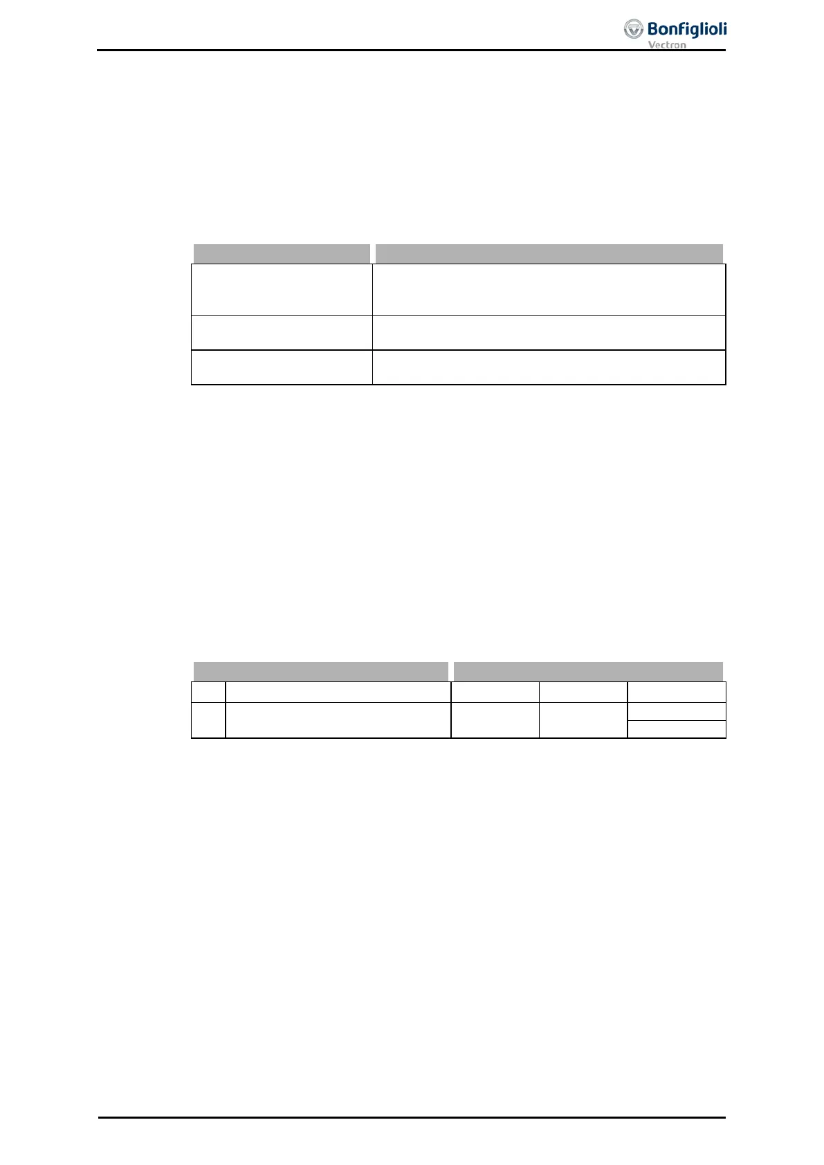
0 -
No message
The intervention of a controller is not reported.
The controllers influencing the operating behavior are
displayed in the Controller status 275 parameter.
1 –
Warning Status
The limitation by a controller is displayed as a warning
by the control unit.
11 –
The limitation by a controller is displayed as a warning
by the control unit and the LED's.
Refer to chapter 15.3.8 Warning Mask and 21.3 Controller Status for a list of control-
lers and further possibilities to evaluate the controller states.
13.4 IDC Compensation Limit
At the output of the frequency inverter a DC component can occur in the output cur-
rent due to unbalances. This DC voltage component can be compensated by the fre-
quency inverter. The maximum output voltage of the compensation is set with pa-
rameter
IDC compensation limit 415
. If a higher voltage than the set limit is needed
for the compensation of a DC voltage component, error “F1301 IDC COMPENSA-
TION” is triggered.
If this fault occurs, it shou
ld be checked whether the load is defective. The voltage
limit may have to be increased.
If the parameter IDC compensation limit 415 is reduced to zero, the DC compensa-
415 IDC Compensation Limit 0.0 V 1.5 V
The factory setting of parameter
415
depends on the setting of
parameter Configuration 30:
Configurations 1xx
Configurations 2xx / 4xx / 5xx / 6xx
06/13 Operating Instructions ACU 151
 Loading...
