14 Reference Values
The ACU series frequency inverters can be configured specific to the application and
enable customer-specific adaptation of the module hardware and software structure.
14.1 Frequency Limits
The output frequency of the frequency inverter and thus the speed setting range are
defined by the parameters Minimum frequency 418 and Maximum frequency 419
The corresponding control methods use the two limit values for scaling and calculat-
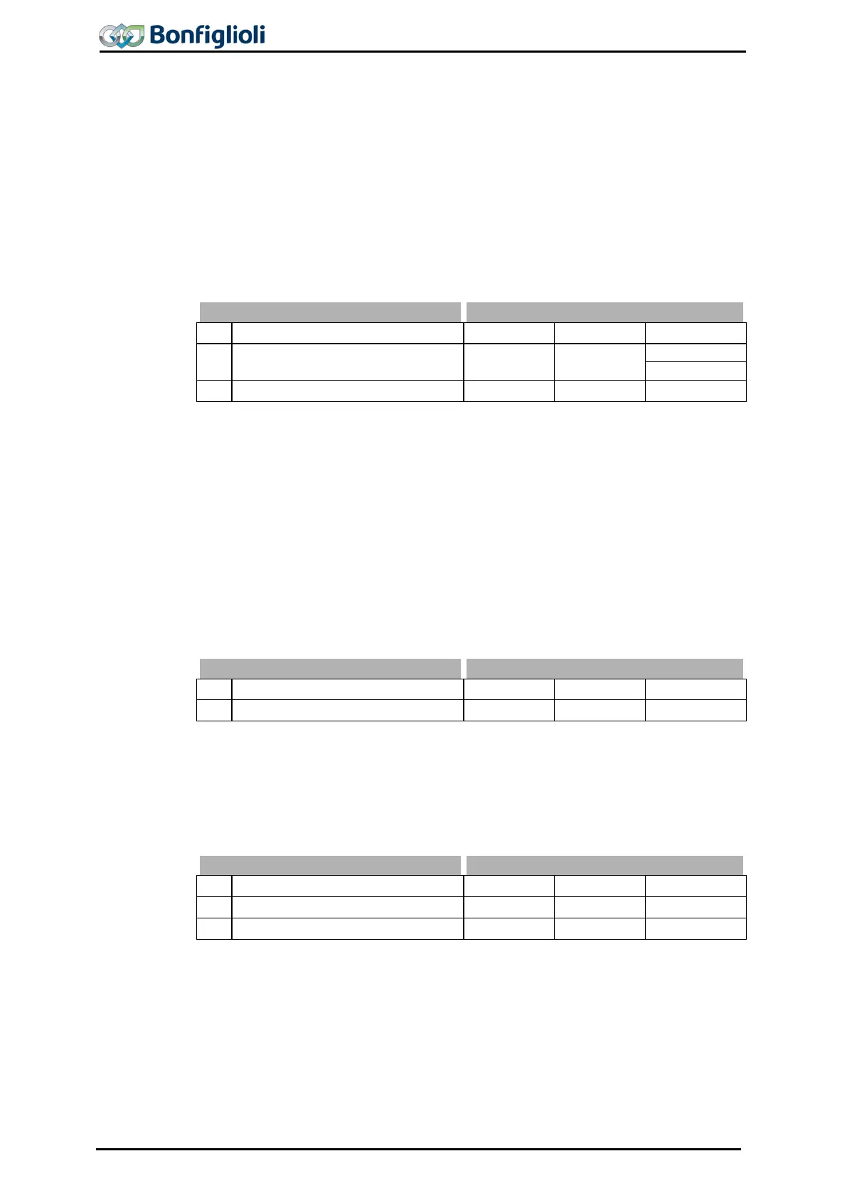
Parameter Settings
No. Description Min. Max. Fact. sett.
418 Minimum Frequency 0.00 Hz 999.99 Hz
419 Maximum Frequency 0.00 Hz 999.99 Hz 50.00 Hz
The factory setting is dependent on the adjustment of parameter Configuration 30:
1)
3.5 Hz in configurations 1xx, 4xx, 6xx
2)
0.00 Hz in configurations 2xx, 5xx
14.2 Slip Frequency
The torque-forming current component and thus the slip frequency of the 3-phase
machine depend on the required torque in the case of the field-
methods. The field-oriented control method also includes the parameter Slip frequen-
cy
719
to limit the torque in the calculation of the machine model. The rated slip
calculated from the rated motor parameters is limited in accordance with the Slip
frequency 719 which is parameterized as a percentage.
14.3 Percentage Value Limits
The setting range of the percentages is defined by the parameters Minimum refer-
ence percentage 518 and Maximum reference percentage 519
. The relevant control
methods use the two limit values for scaling and calculating the frequency.
518 Minimum Reference Percentage 0.00 % 300.00 % 0.00 %
519 Maximum Reference Percentage 0.00 % 300.00 % 100.00 %
14.4 Frequency reference channel
The different functions for the defining the reference frequency are connected via the
frequency reference value channel. The Reference frequency source 475
determines
the additive assignment of the available reference value sources depending on the
hardware installed.
154 Operating Instructions ACU 06/13
 Loading...
