The setting of the percentage limits of the comparators enables the following logical
links. The comparison with signs is possible in the corresponding operation modes of
the comparators.
1
on
above
0
off
below
%
1
on
above
0
off
below
%
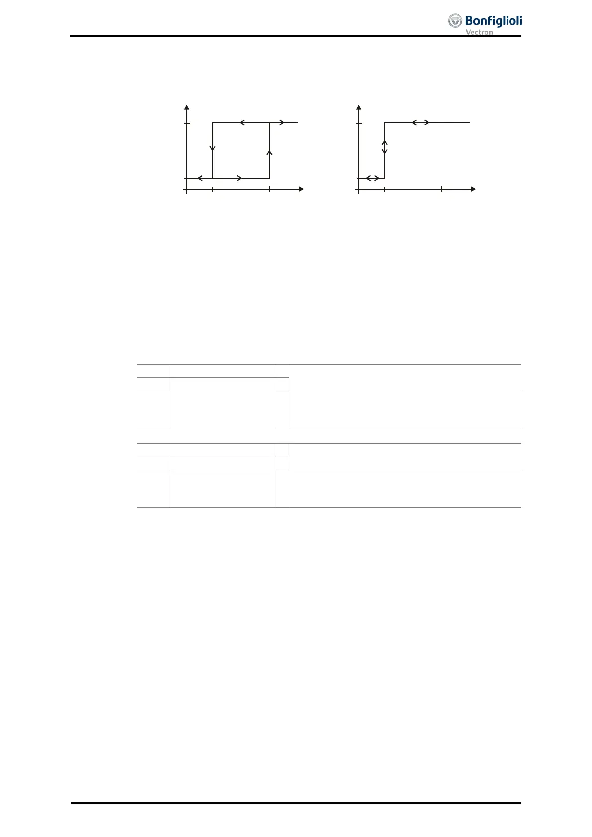
Op. Mode Comparator 1 540 = 7- Abs. Actual Frequency
Comparator On above 541 = 80.00 % (of Maximum Frequency 419)
Comparator Off below 542 = 50.00 % (of Maximum Frequency 419)
Maximum Frequency 419. = 50.00 Hz
Comparator will switch on if Actual Frequency 241 > 40.00 Hz
Comparator will switch off if Actual Frequency 241 < 25.00 Hz
Digital signals indicate the result of the comparison.
The comparison – selected via Op. Mode Compar-
ator 1 540 – is true.
172 -
Negated Output Com-
parator 1
1)
The comparison – selected via Op. Mode Compar-
ator 1 540 – is true. The output level of the com-
The comparison – selected via Op. Mode Compar-
ator 2 543 – is true.
174 -
Negated Output Com-
parator 2
1)
The comparison – selected via Op. Mode Compar-
ator 2 543 – is true. The output level of the com-
1)
For linking with inverter functions
15.5.3 Function table
The function table allows to link external digital signals and internal logic signals of
the frequency inverter with each other. Besides standard AND, OR and XOR combina-
tions, different m
ore advanced logic functions like RS Flip Flop are available. The
corresponding output value can be used for further logic instructions and digital out-
puts. The logic instructions can be linked with each other for any complex intercon-
nections.
Up to 32 logic instructions allow flexible adoption of various input signals.
A drive should start when:
− the enable signal AND the S5IND signal are set
OR
− the enable signal AND the S6IND signal are set.
Refer to the application manual “Function table” for a more detailed description.
06/13 Operating Instructions ACU 205
 Loading...
