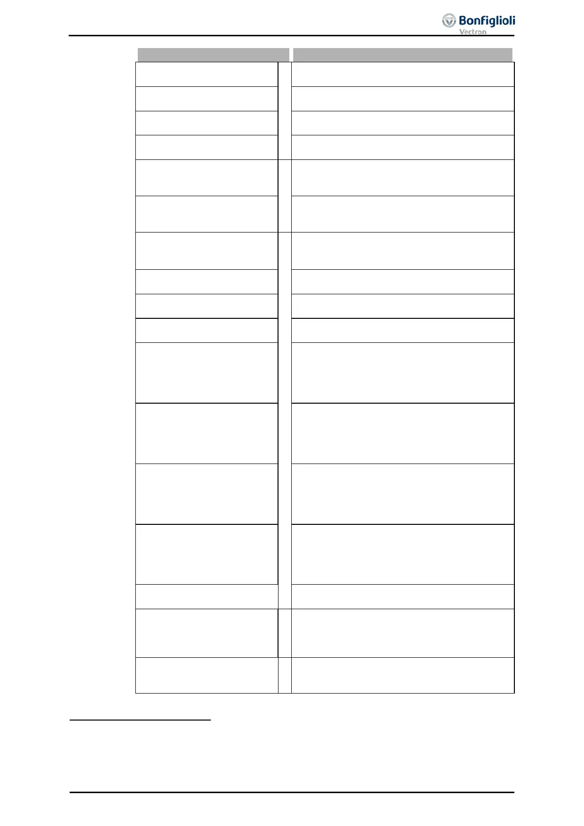
750 - OUT-PZD3 Boolean
11
Process data for Profibus-communication. Module
CM-PDP with Profibus interface is necessary.
751 - OUT-PZD4 Boolean
Process data for Profibus-communication. Module
CM-PDP with Profibus interface is necessary.
752 - OUT-PZD5 Boolean
Process data for Profibus-communication. Module
CM-PDP with Profibus interface is necessary.
753 - OUT-PZD6 Boolean
Process data for Profibus-communication. Module
CM-PDP with Profibus interface is necessary.
to
to
12
Source of CAN objects for CANopen-
communication. Module CM with CAN interface
to
Out 1 to Obj 0x3005
Source of the demultiplexer output for CANopen-
communication. Module CM with CAN interface
876 -
Position Comparator
Out
13
The current actual value is in the range between
Switch-on position 1243 and Switch-off posi-
877 -
Position Comparator
Out inverted
Operation mode 876 inverted.
887 - MBC: Start Clockwise
Message clockwise operation of positioning con-
troller.
888 -
MBC: Start Anticlock-
wise
Message anticlockwise operation of positioning
controller.
891 -
Motion-Block Digital
Signal 1
Message on status of a travel order during a posi-
tioning operation. The conditions set for parame-
ter
Digital Signal 1 1218 were fulfilled. „Start“,
„Reference value reached“ and „End“ of a travel
892 -
Motion-Block Digital
Signal 2
Message on status of a travel order during a posi-
tioning operation. The conditions set for parame-
ter
Digital Signal 2 1219 were fulfilled. „Start“,
„Reference value reached“ and „End“ of a travel
893 -
Motion-Block Digital
Signal 3
Message on status of a travel order during a posi-
tioning operation. The conditions set for parame-
ter
Digital Signal 3 1247 were fulfilled. „Start“,
„Reference value reached“ and „End“ of a travel
894 -
Motion-Block Digital
Signal 4
Message on status of a travel order during a posi-
tioning operation. The conditions set for parame-
ter
Digital Signal 4 1248 were fulfilled. „Start“,
„Reference value reached“ and „End“ of a travel
895 to 898
Operation modes 891 to 894 inverted (LOW ac-
tive).
910
to
925
Output DeMux Bit 0
to
Output DeMux Bit 15
14
Bit 0 to Bit 15 on output of de-multiplexer; de-
multiplexed process data signal via system bus or
Profibus on input of multiplexers (parameter
to
to
15
Output signals from FT-instructions of the func-
tion table.
11
Refer to the operating instructions of the expansion modules with Profibus interface.
12
Refer to the operating instructions of the expansion modules with CAN interface.
13
Refer to the application manual “Positioning” for further details.
14
Refer to the operating instructions of the expansion modules with system bus or Profibus interface.
15
Refer to the application manual “Function Table” for further details.
06/13 Operating Instructions ACU 195
 Loading...
