EasyManua.ls Logo

BONFIGLIOLI active User Manual

BONFIGLIOLI active
50 pages
To Next Page IconTo Next Page
To Previous Page IconTo Previous Page
Page #27 background imageLoading...
Page #27 background image
2506/05
06/05 25
8.5.7 0x6049/n Velocity deceleration
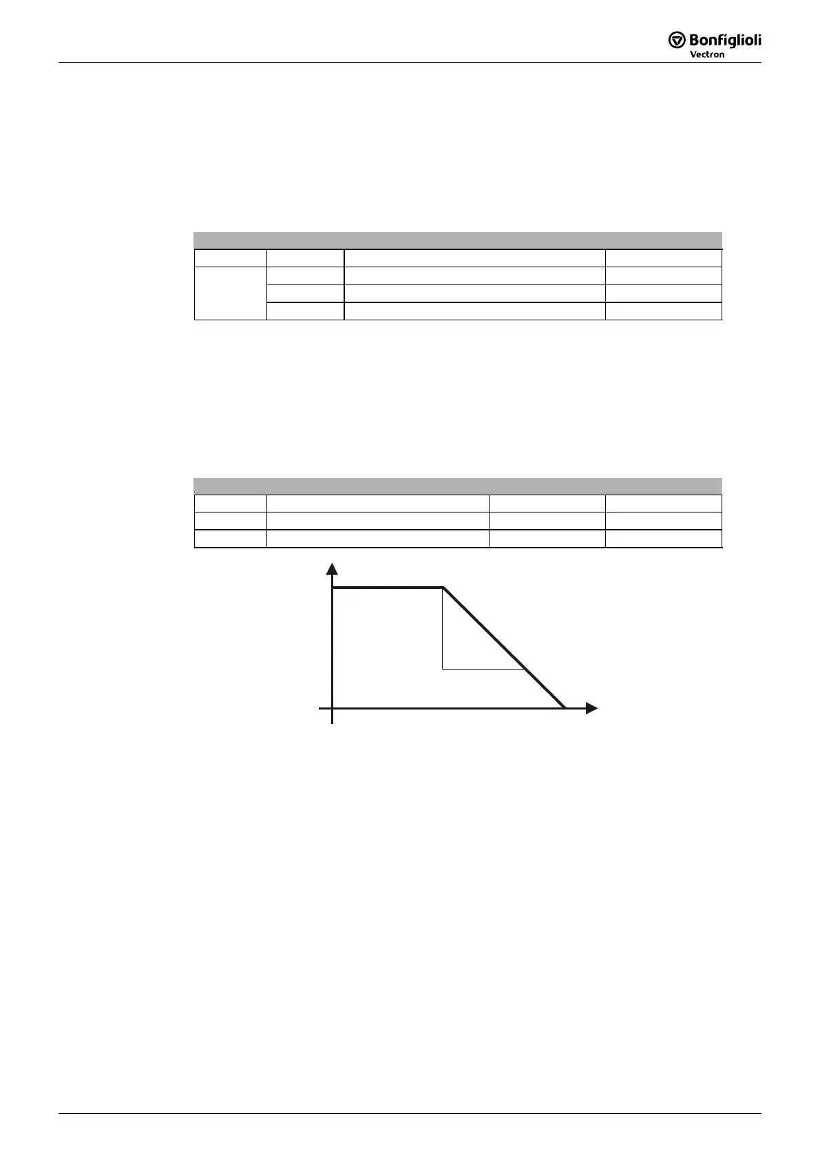
The change of speed and deceleration time are set with the object velocity
deceleration. The object velocity deceleration defines the value delta speed in the
same notation (RPM) as the ob
j
ect tar
g
et velocity via subindex 1 and the value delta
time in seconds via subindex 2.
Velocity acceleration
Index Subindex Meaning Value
0x6049 0 Number of entries (unsigned 8) 2
1 Delta speed (RPM) (unsigned 32)
2 Delta time (sec) (unsigned 16)
The gradient of the frequency in deceleration is internally written onto the parameters
Deceleration (clockwise) 421 and Deceleration (anti-clockwise) 423 in the first data
set. The two parameters are set to the same value, which is specified via the ob
j
ec
t
velocity acceleration.
The gradient is internally changed by chan
g
in
g
the ob
j
ects delta time or delta speed.
Chan
g
in
g
the ob
j
ect value for delta speed, which is internally converted into the uni
t
Hz, is sufficient for a change of the gradient.
Parameter Setting
No. Object Min. Max.
0x6049/1 Delta speed (RPM) 1 65536
0x6049/2 Delta time (sec) 1 65535
delta speed
delta time
time
speed
Note:
T
he ob
j
ect delta time is always set to the ob
j
ect value = 1 after the rese
t
of the frequency inverter.

Table of Contents

Other manuals for BONFIGLIOLI active

Questions and Answers:

BONFIGLIOLI active Specifications

General IconGeneral
BrandBONFIGLIOLI
Modelactive
CategoryDC Drives
LanguageEnglish

Summary

1 General safety and application information

1.2 Proper use

Describes the intended use of frequency inverters and compliance with directives.

1.5 Electrical connection

Information and standards for electrical connection of frequency inverters.

3 Assembly of the CANopen communication module CM-CAN

4 Plug occupancy/bus connection/line

5 Baud rate setting/line lengths

6 Setting node address

7 Operational behaviour if the bus connection fails

8 Objects

8.6 Manufacturer Objects (0x2000/n)

Manufacturer-specific objects for parameterization.

9 Control / reference value

9.1 Control via Contacts

Control method using contact inputs.

9.2 Control via State Machine

Control method using internal state machine.

9.3 Control via Remote Contacts

Control method using remote contacts.

9.4 Reference Value / Actual Value

How reference and actual values are handled.

10 Parameter list

Related product manuals