3506/05
34 06/05
9 Control / reference value
A control
ives its control commands (control word) to the frequency inverter via the
object 0x6040/0 control word and receives the information about its status (status
word) back via the object 0x6041/0 status word.
A control
ives its reference speed to the frequency inverter (mapped onto the
reference line value) via the ob
et velocity and receives the actual
speed via the object 0x6044/0 control effort.
Note:
ects 0x6040/0 control word, 0x6041/0 status word, 0x6042/0
tar
et velocity and 0x6044/0 control effort are contents of the available
Rx/TxPDO’s. Detailed information is to be found in the previous chapters.
In the followin
explanations and descriptions, the standardized
designations control word and status word are used.
he control of the frequency inverter can be done with three operation modes. They
are set via the data set change-over capable parameter
Local/Remote 412.
Parameter Setting
No. Description Min. Max. Fact. sett.
412 Local/Remote 0 44 44
For operation on the CANopen, only the settin
s 0, 1 and 2 are relevant. The further
settings relate to the possibilities of control via the KP500 control unit.
Operation mode Function
0 -Control via contacts
he Start and Stop command as well as the statement
of the direction of rotation are via digital signals.
1 -
Control via
state machine
The Start and Stop command as well as the statement
of the direction of rotation are via the DRIVECOM State
machine of the communication interface.
2 -
Control via
remote contacts
he Start and Stop command as well as the statement
of the direction of rotation are via logic signals by the
communication protocol.
Control word STW and state word ZSW have differin
contents as a function of the
operation mode. In each case, all or only some of the bits in the control word are
relevant and also only certain feedbacks are possible via the status word. These are
then explained in the descriptions of the three possible operation modes.
Control and state word have been created accordin
to DRIVECOM. In this way, there
is compatibility to CANopen DS402.
Note:
The parameter
Local/Remote 412 is data set change-over capable. Thus,
switchin
over between various operation modes via the data set
selection is possible. For example, it is possible to control an frequency
inverter via the bus and to activate a local emergency operation if the bus
master breaks down. This switch-over is also visible via the state word
(Bit Remote).
The data set change-over can be done locally at the frequency inverter via contact
inputs or via the bus. For the data set change-over via the bus, the parameter
ata
set selection
414 is used.
Parameter Setting
No. Description Min. Max. Fact. sett.
414 Data set selection 0 4 0
With
Data set selection 414 = 0, the data set switch-over via contact inputs is active.
If
Data set selection 414 has been set to 1, 2, 3, or 4, the data set selected in this
way has been activated. The data set switch-over via the contact inputs is then
deactivated.
Via the parameter
Active data set 249 the data set currently selected can be read out.
Active data set 249 states the activated data set with the value 1, 2, 3 or 4. This is
independent of whether the data set change-over has been done via control inputs o
r
via
Data set selection 414.
9.1 Control via contacts
In the operation mode control via contacts (
Local/Remote 412 = 0) the frequency
inverter is controlled via the contact inputs S2IND to S6IND. The meanin
of these
inputs can be seen from the operatin
instructions. The control word in is not relevan
for this operation mode.
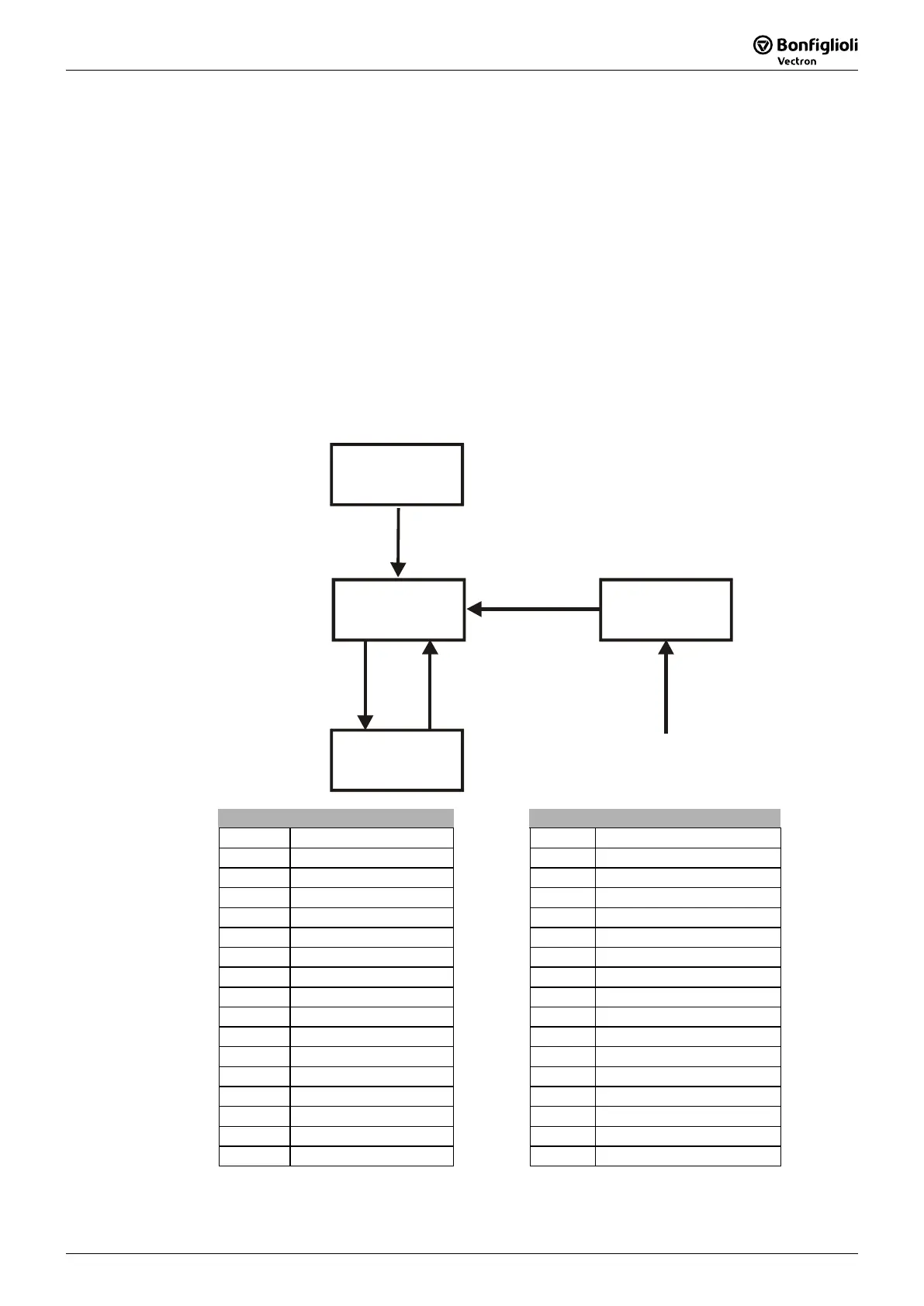
State machine:
The values contained in the states report give the feedback about the state word
(Bit 0 to Bit 6).
Power on
Initialisation
Ready
0x23
Operation
enabled
0x27
Fault
0x08
Enable
on
Enable
off
Quitt fault
from any state
Control word State word
Bit No. Name Bit No. Name
0 - 0 Ready to switch on
1 - 1 Ready
2 - 2 Operation enabled
3 - 3 Fault
4 - 4 Voltage -inhibited
5 - 5 Quick-stop
6 - 6 Switch on inhibit
7 - 7 Warning
8 - 8 -
9 - 9 Remote
10 - 10 Reference value reached
11 - 11 Limit value reached
12 - 12 -
13 - 13 -
14 - 14 -
15 - 15 Warning 2