3906/05
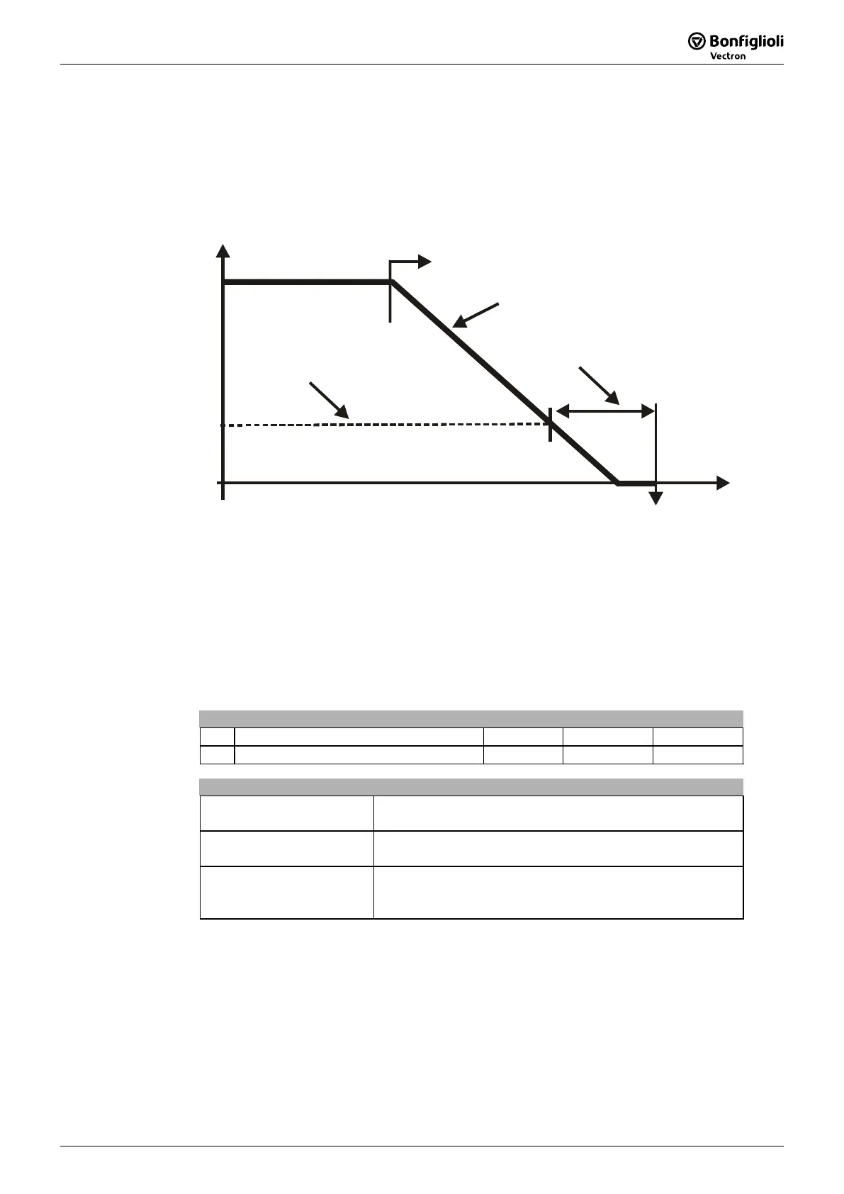
9.2.1 Behavior in quick stop
In this, the parameters
Switch-off threshold
637 (percent of fmax) and Holding time
638 (holding time after falling short of the switch-off threshold) are relevant. In a
quick stop, the drive is shutdown via the emergency stop ramps (
mergency stop
clockwise
424 or Emergency stop anti-clockwise 425).
t
f
s
Start quick stop
Switch-off threshold.
637
Holding time
638
Emergency stop clockwise
424
425
mergency stop anticlockwise
OF F,
s
tatus changed
If frequency/speed zero has been reached during the holding time, the drive
continues to be supplied with direct current until the switch-off time has expired. With
this measure, there is an assurance that the drive is stationary in a change of state.
9.2.2 Behavior in transition 5
The behavior in transition 5 from "Operation enabled" to "Switched on" can be
parameterized. The behavior is set via parameter
State transition 5 392.
Parameter Setting
No. Description Min. Max. Fact. sett.
392 State transition 5 0 2 2
Operation mode Function
0 -Coast to stop
immediate transition from "Operation enabled“ to "Ready“,
free stoppage of the drive
1 -DC brake
activation of DC brake, with the end of DC braking, there
is the change from "Operation enabled“ to "Ready“
2 -Ramp
transmission with normal stop ramp, after reaching
standstill, there is a change from "Operation enabled“ to
"Ready“
Note: Setting operation mode "1 - DC brake“ is only possible in applications with
v/f characteristic (e.g. configuration 110), as other applications do no
know such an operation mode.
If the frequency inverter is operated with a confi
uration which does no
know the DC braking operation mode (e.g. configuration 210, field-
orientation speed controlled), value "1" cannot be set. It is also not
offered in the selection menus of the KP500 control unit or the VPlus
program.