06/0538
Note: A fault occurring leads to a switch-over to the "Fault" state. The
acknowledge of the fault is done by a positive edge of Bit 7.
A fault can only be acknowledged 15 seconds after the occurrence of the
fault, as a blocking time is active internally.
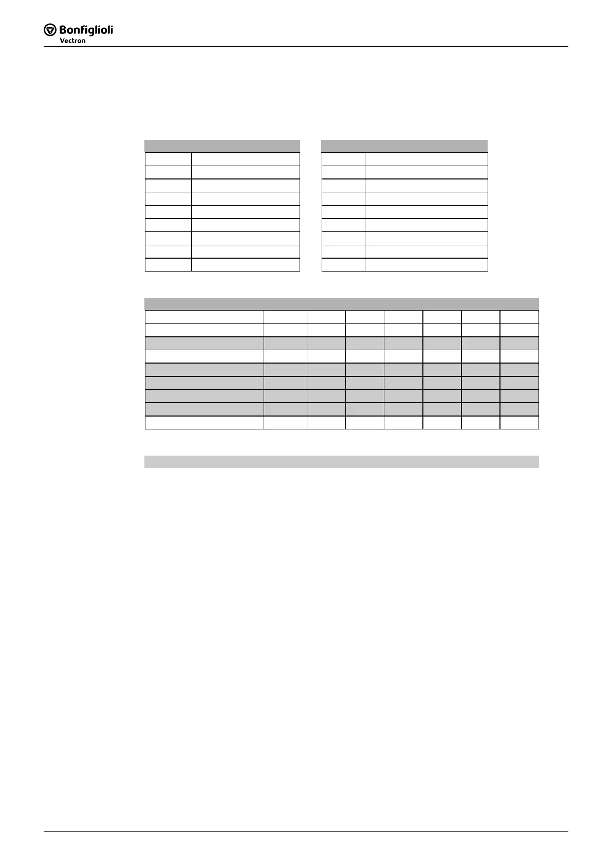
State word State word
Bit No. Name Bit No. Name
0 Ready to switch on 8 -
1 Ready 9 Remote
2 Operation enabled 10 Reference value reached
3 Fault 11 Limit value reached
4 Voltage inhibit 12 -
5 Quick stop 13 -
6 switch on inhibit 14 -
7 Warning 15 Warning 2
The state word reflects the operation state.
State word
Meaning HEX (*) Bit 6 Bit 5 Bit 3 Bit 2 Bit 1 Bit 0
Switched-off 0x00 0 x 0 0 0 0
Switch-on inhibit 0x40 1 x 0 0 0 0
Ready to switch-on 0x21 0 1 0 0 0 1
Quick-stop 0x07 0 0 0 1 1 1
Ready 0x23 0 1 0 0 1 1
Operation enabled 0x27 0 1 0 1 1 1
Fault 0x08 0 x 1 0 0 0
Fault reaction active 0x0F 0 x 1 1 1 1
(*) without considering bits 7 to bit 15
The shaded commands are the commands relevant for the simplified state machine.
The Warning bit "Bit No. 7" can be set at any time. It displays an device-internal
warning message. The evaluation of the warning available is done by reading out the
warning status with the parameter
Warnings 270.
The Remote bit "Bit No. 9" is set if the operation mode control via state machine
(
Local/Remote 412 = 1) has been set and the hardware release is available.
Logic linking of the digital control signals:
( S1IND AND ( S2IND OR S3IND ) )
Only if the logic linking is true the frequency inverter can be controlled via the control
word.
The bit Reference value reached "Bit No. 10" is set when the reference value
specified has been reached. In the special case of power failure re
gulation, the bit is
also set if the power failure regulation has reached the frequency 0 Hz (see operating
instructions). For "Reference value reached“ there is a hysteresis (tolerance range),
which can be set via the parameter
max. Control deviation 549 (see operatin
instructions).
The bit Limit value active "Bit No. 11" displays that an internal limit is active. This
can, for example, be the present current limit, the torque limit or the over-voltage
limit. All the functions lead to the reference value being quit or not reached.
The bit Warning 2 "Bit No. 15" reports a warning which leads to a fault switch-of
of the frequency inverter within a short time. This bit is set if there is a warnin
fo
motor temperature, heat sink/inside temperature, Ixt monitorin
or mains phase
failure.