— To the extent necessary, amply secure the surrounding area
when performing maintenance. Cordon of
f the working area
with a red and white safety chain and a warning sign.
— Relieve the pressure in the Börger machine according to
Ä
Chapter 6.1.2 “Pressure relief” on page 109.
— Open the quick-release cover in accordance with
Ä
Chapter
6.3.2 “Opening and closing the quick-release cover”
on page 125.
— Clean the interior of the Börger machine as described in
Ä
Chapter 6.1.3 “Cleaning the inside” on page 111.
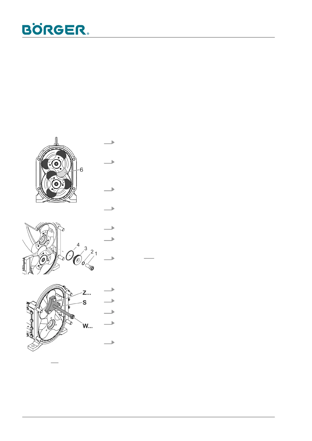
1.
Remove at least one lobe tip (6) according to
Ä
“Removing
and replacing the MIP
®
lobe tips” on page 136.
2. Move the screw rotors into the position shown here by
turning one carrier shaft [W] clockwise using a suitable hex-
agon socket wrench.
3. Block the carrier shafts by clamping an object with no sharp
edges between the rotors, e.g. a lint-free cloth.
4. Loosen the hexagon socket head cap screws (1) using a hex-
agon socket wrench, then remove them.
5. In each case, remove the sealing washer (2).
6. In each case, remove the cover disk (3) and O-ring (4) using
a suitable hook or two slotted screwdrivers.
7. For rotors with threaded bores (see Fig. 10) screw three
screws with washers (S) into the threaded bores through the
outer bores of the auxiliary puller [Z...].
8. Screw the auxiliary puller [Z...] into the rotor puller [W
...].
9. Remove the first rotor from the carrier shaft [W].
10. Remove the second rotor accordingly
.
11. Thoroughly clean all parts and the pump chamber before
reinstalling removed parts.
12. Check all removed parts for wear and only reuse them if they
are undamaged.
Fig. 10: Rotors with threaded bores
Maintenance and Repairs
BA-Classic FL_en-US, 03.05.2018www.boerger.de / www.boerger.com146
 Loading...