Do you have a question about the Bosch CCS800 and is the answer not in the manual?
Records changes made to the manual over revisions.
Explains the manual's purpose, scope, and target audience.
Lists other relevant manuals and documents for the system.
Defines the types of alerts used in the manual (Note, Caution, Warning, Danger).
Outlines repair policies, warranty conditions, and service periods.
Provides a template for Return Material Authorization requests for repairs.
Introduces the CPSU, its role, and power supply functions.
Describes the CPSU model with Acoustic Feedback Suppression.
Details the AFS module, its board function, and block diagram.
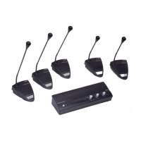
Explains the function of the delegate unit in the discussion system.
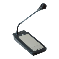
Describes the chairman unit and its priority functions.
Illustrates audio signal levels for delegate and chairman units.
Details the top and rear controls and indicators of the CPSU.
Explains controls and indicators for delegate and chairman units.
Provides specifications for the power supply unit.
Details the procedure for adjusting the microphone stem sensitivity.
Discusses the need for regular cleaning based on usage.
Outlines replacement and centralized repair procedures for defective units.
Covers electrical, mechanical, and microphone repair procedures.
Describes functional tests for delegate and chairman units.
Explains control lines and modes for chairman/delegate units.
Lists measurement procedures for the CPSU.
Lists measurement points and their signals on the CPSU board.
Outlines procedures to check delegate/chairman unit operation.
Measures the supply current from V+ on the delegate/chairman unit.
Measures internal supply voltages on delegate/chairman units.
Detects the presence of a delegate or chairman unit.
Identifies if a unit is a delegate or chairman unit.
Tests the microphone switch and the light-ring indicator.
Checks internal signals for delegate and chairman units.
Tests specific internal signals relevant only to delegate units.
Tests chairman unit modes like Chairman Only and Priority.
Lists measurement points and signals for delegate/chairman boards.
Explains changes in the new microphone head construction and light output.
Lists type numbers and hardware releases for implementation.
Details electrical changes for new microphone heads.
Instructions for preparing to replace the microphone capsule.
Steps for disassembling the microphone cap and capsule.
Steps for reassembling the microphone unit with a new capsule.
Details pin assignments and colors for trunk cables.
Lists extension cable specifications and connector types.
Lists tools and materials for mounting a new CPSU board.
Provides steps for drilling holes to mount the new CPSU board.
Explains how to order spare parts through local Bosch representatives.
Lists mechanical and printed board spare parts for CPSU units.
Lists mechanical, service, and board spare parts for delegate/chairman units.
Lists spare parts for the microphone head assembly.
Shows an exploded view of the CPSU components for identification.
Displays the physical layout of components on the CPSU board.
Identifies measurement points on the CPSU board with signal descriptions.
Shows circuit diagrams for CPSU supply and logic sections.
Illustrates CPSU circuit diagrams for gain control and mode selection.
Displays CPSU circuit diagrams for audio input/output functions.
Shows CPSU circuit diagrams for external microphone input.
Shows the physical layout of the AFS PCB with jumpers and connectors.
Provides an exploded view of the delegate/chairman unit components.
Displays the component layout of the delegate unit board.
Identifies measurement points on delegate/chairman unit boards.
Shows the circuit diagram for the delegate unit.
Displays the component layout of the chairman unit board.
Shows the circuit diagram for the chairman unit.
Details the microphone assembly, including exploded view, LED diagram, and wiring.
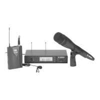
| Output Impedance | 200 ohms |
|---|---|
| Type | Condenser |
| Connector | XLR |
| Power Supply | Phantom power 48V |
| Nominal sensitivity | -38 dB |