CCS800 | Service manual | Chapter 7 | Diagnostics and faultfinding en | 26
Bosch Security Systems | 2005-01| 3922 880 21112
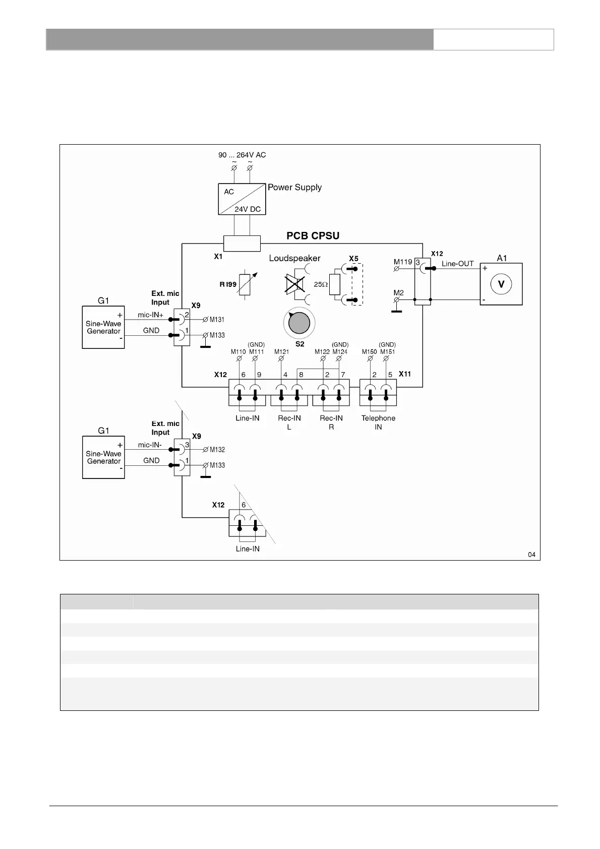
7.3.7 External microphone input to line out measurement
Connect successively a sine-wave generator to the left and right external microphone input connections, (“MIC-IN+”
(M131) and “MIC-IN-” (M132) ) related to GND (M133).
NOTE: be sure that the gain control potentiometer (R199) of the external microphone input is set to the middle position.
Input setting G1: X130 p-2 related to X130 p-1 (GND) and X130 p-3 related to X130 p-1 (GND), see table below.
Settings for G1 Measurement results for A1
Amplitude Frequency Amplification
Nominal level -56 dBV (1.6 mVrms) 1 kHz -15 dBV ± 2dB (85dB SPL)
Maximum level -31 dBV (28.2 mVrms) 1 kHz +10 dBV ± 2 dB (110 dB SPL)
Bandwidth -56 dBV (1.6 mVrms) 125 Hz -3dB ± 2dB related to nom. level at 1kHz
Bandwidth -56 dBV (1.6 mVrms) 12.5 kHz -0.5dB ± 1dB related to nom. level at 1kHz.
Mute level: set
S2 to chairman
only mode
-56dBV (1.6 mVrms) 1 kHz < -74 dBV (selective) or < -74 dBV (A-weighted)
• Set S2 back to position AUTO 1.
Reference: M119 See Ch. 13.6
M131, 132, 133, R199 See Ch. 13.7