CCS800 | Service manual | Chapter 13 | Illustrations en | 51
Bosch Security Systems | 2003-50 | 3922 880 21112
13 Illustrations
Index
13.1 Exploded view CPSU.
13.2 Board layout CPSU.
13.3 Measuring points CPSU board.
13.3.1 Bottom view CPSU board section mounted in top cover.
13.4 Circuit diagrams CPSU (sh 1/4) — Supply and logic.
13.5 Circuit diagrams CPSU (sh 2/4) — Gain control and mode select.
13.6 Circuit diagrams CPSU (sh 3/4) — Audio input and output.
13.7 Circuit diagrams CPSU (sh 4/4) — External microphone input.
13.8 Board layout AFS PCB.
13.8.1 Jumpers and connectors.
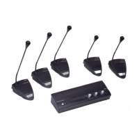
13.9 Exploded view delegate/ chairman unit.
13.10 Board layout delegate unit.
13.11 Measuring points delegate and chairman unit.
13.12 Circuit diagram delegate unit.
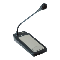
13.13 Board layout chairman unit.
13.14 Circuit diagram chairman unit.
13.15 Microphone assembly.
13.15.1 Exploded view microphone head.
13.15.2 Led diagram and board layout.
13.15.3 Wiring of the microphone assembly.
Note
Illustrations from 13.1 to 13.4 are in A3 format.