CCS800 | Service manual | Chapter 7 | Diagnostics and faultfinding en | 29
Bosch Security Systems | 2005-01| 3922 880 21112
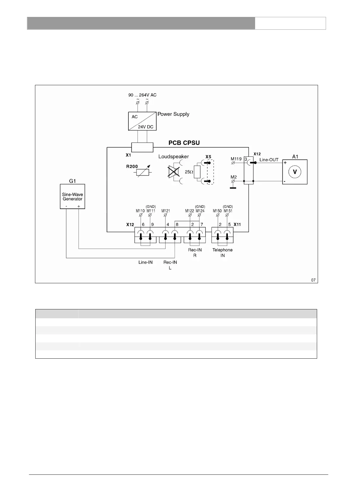
7.3.10 Recorder-in to Line-out measurement
Remove the interconnections of REC-IN-L and REC-IN-R and connect successively a sine-wave generator to the REC-IN-
L and REC-IN-R connector. Measure the output signal at the LINE-OUT connector.
NOTE: be sure that the gain control potentiometer (R200) of the recorder input is set to the middle position.
Input setting G1: M121 & M122 related to M124 (GND), see table below.
Settings for G1 Measurement results for A1
Amplitude Frequency Amplification
Nominal level -20dBV (100mV
rms
) 1kHz -16.5dBV ± 2dB (85dB SPL)
Maximum level +5dBV (1.78V
rms
) 1 kHz +9.5dBV ± 2dB (110dB SPL)
Bandwidth -20dBV (100mV
rms
) 125 Hz -0.5dB ± 1dB related to nom. level at 1kHz
Bandwidth -20dBV (100mV
rms
) 12.5 kHz -1dB ± 1dB related to nom. level at 1kHz.
Reference: M119, R300 See Ch. 13.6