CCS800 | Service manual | Chapter 8 | New mic assy on an old del-/ chairman unit en | 42
Bosch Security Systems | 2005-01| 3922 880 21112
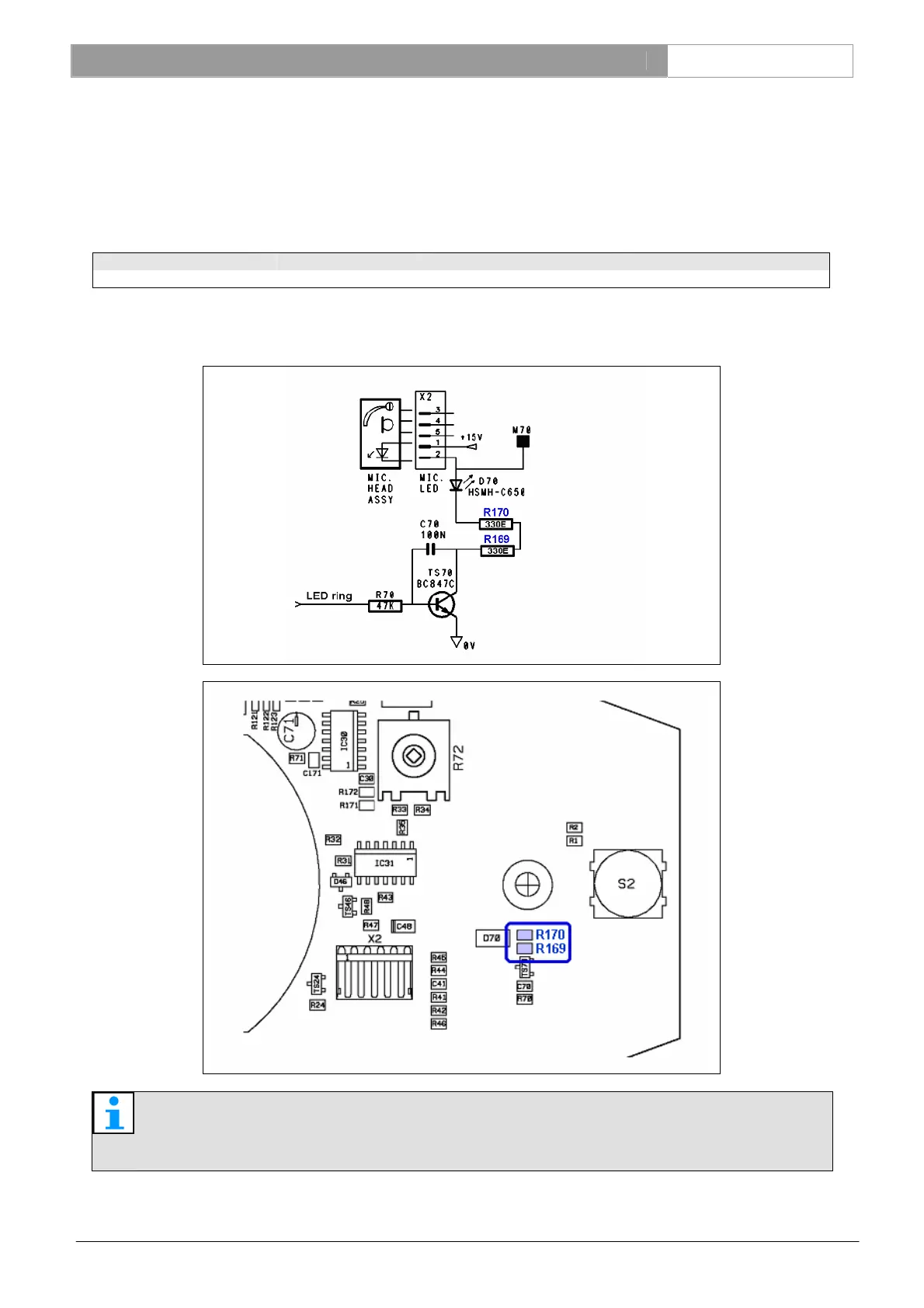
8.4 Field changes of components on the main board
In case the microphone assembly has been replaced and light output of the led ring is too low in respect to the installed
units, change the components R169 and R170 on the main board in order to increase the led current.
8.4.1 Delegate- and chairman unit component values
Type numbers Hardware release Old mic head led resistors New mic head led resistors
LBB 3330 & LBB 3331
≤ 01-02
R169 = 330E & R170 = 330E R169 = 150E & R170 = 180E
8.4.2 Diagram and board layout of HW 01-02
Note
For current version diagram and board layout see chapter 13.10 and 13.12.