CCS800 | Service manual | Chapter 7 | Diagnostics and faultfinding en | 31
Bosch Security Systems | 2005-01| 3922 880 21112
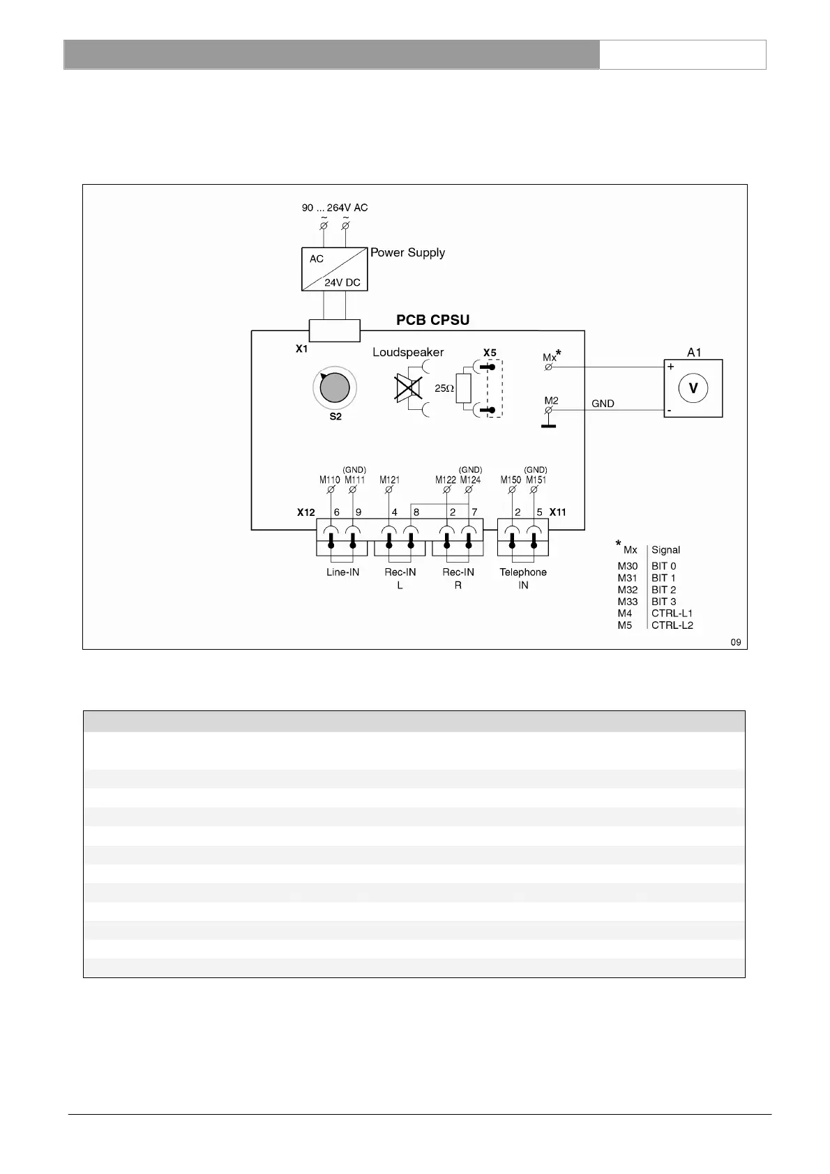
7.3.12 Control line test with mode switch (A)
By use of a combination of different voltage levels at CTRL-L1 and CTRL-L2 each mode of the CPSU can be passed on
to the Delegate and Chairman units.
Set the “mode switch” (S2) is each position and measure the voltages at M30, M31, M32, M33, M4 and M5 related to M2
(GND).
Mode switch Measurement values for A1 (V)
Position
(S2)
M33
(bit 3)
M32
(bit 2)
M31
(bit 1)
M30
(bit 0)
M4
(Control-L1)
M5
(Control-L2)
Auto-1 0 10 0 0 2.5 2.9
Auto-2 0 10 0 10 2.5 2.9
Auto-3 0 10 10 0 2.5 2.9
Auto-4 0 10 10 10 2.5 2.9
Open-1 0 15 0 0 2.5 5.7
Open-2 0 15 0 10 2.5 5.7
Open-3 0 15 10 0 2.5 5.7
Open 4 0 15 10 10 2.5 5.7
Override 10 10 0 0 1.0 5.7
Chairman only 10 10 0 10 1.0 >14
Test 10 10 10 0 2.5 1.0
Tolerances: 10V ±500 mV and 15V ±750mV
CTRL-L1 levels is ±100mV
CTRL-L2 levels is on 1.0V ±100mV, on 2,9V ±150mV and on 5,7V ±300mV
Reference: M30, 31, 32, 33, S2 See Ch. 13.5
M4, 5 See Ch. 13.7