Home
Bosch
Microphone
CCS800
Bosch CCS800 User Manual
5
of 1
of 1 rating
72 pages
Give review
Manual
Specs
To Next Page
To Next Page
To Previous Page
To Previous Page
Loading...
CCS800 |
Service manual | Chapter 13 | Illustr
ations
en | 67
Bosch Security Systems
| 2003-50 | 3922 880 21112
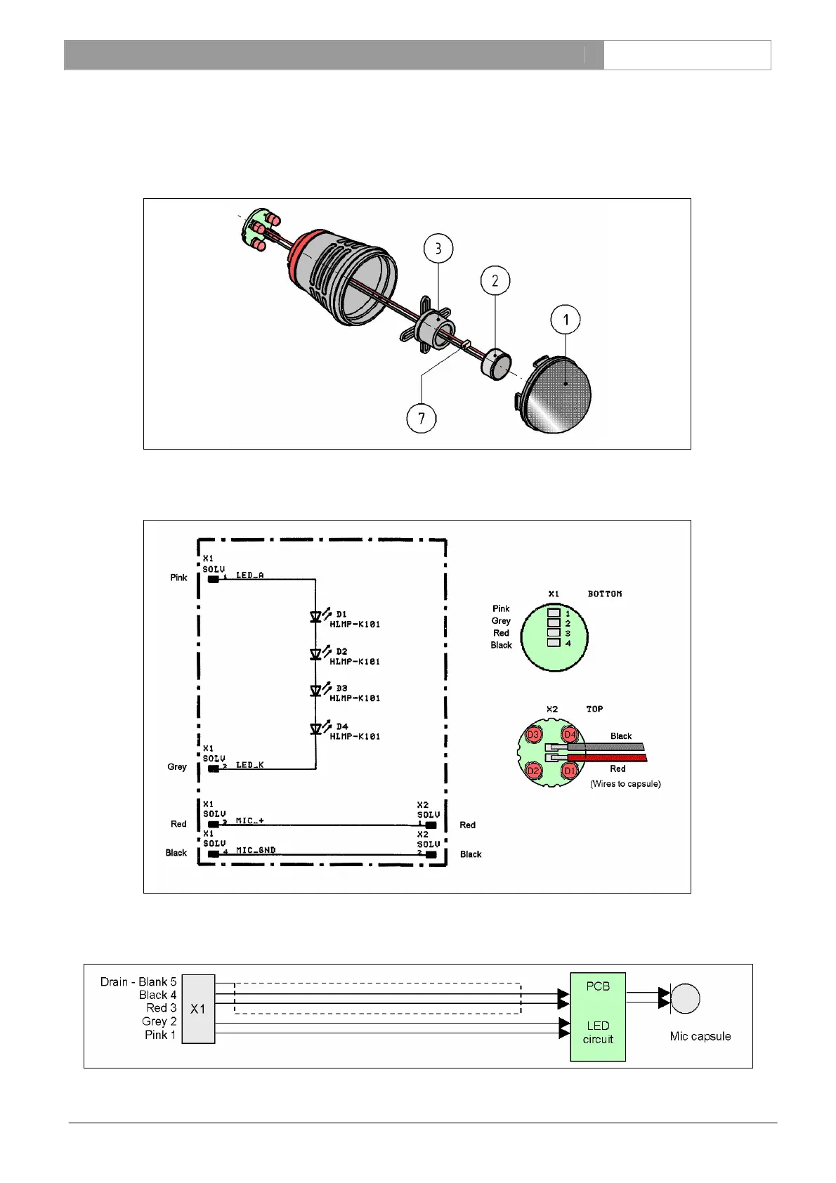
13.15
Microphone assembly
13.15.1
Exploded view microphone head
13.15.2
Led diagram and board layout
13.15.3
Wiring of the microphone assembly
68
70
Table of Contents
Default Chapter
3
Important Safeguards
3
Table of Contents
4
1 General Information
7
Document History
7
About this Manual
7
Related Documentation
7
Alerts
7
1.5 Policy & Procedures
7
Repair Policy
7
Warrantee Conditions
7
Service Period
8
Type Number Survey
8
Example RMA Request Form
9
2 Introduction
10
LBB 3310/00 Control and Power Supply Unit (CPSU)
10
Block Diagram CPSU
10
LBB 3310/10 Control and Power Supply Unit with AFS
11
Block Diagram CPSU with AFS
11
Audio Level Diagram CPSU
12
AFS Module LBB 3310/10)
13
Board Function
13
Block Diagram AFS Board
13
LBB 3330/00 Delegate Unit
14
LBB 3330/50 Delegate Unit with Long Microphone Stem
14
Block Diagram Delegate Unit
14
LBB 3331/00 Chairman Unit
15
LBB 3331/50 Chairman Unit with Long Microphone Stem
15
Block Diagram Chairman Unit
15
Audio Level Diagram Delegate and Chairman Units
16
3 Controls and Indicators
17
Control and Power Supply Unit (CPSU)
17
Delegate and Chairman Units
18
4 Technical Data
19
Power Supply
19
Additional Technical Specification for Test Environment
19
5 Microphone Stem Adjustment
20
6 Maintenance and Repair
22
Preventive Maintenance
22
Corrective Maintenance
22
Workshop Repair
22
Electrical Repair
22
Mechanical Repair
22
Microphone Repair
22
7 Diagnostics and Fault Finding
23
Functional Tests with a Minimized System
23
Testing the Light-Ring
23
Testing the OPEN 1 Mode
23
Testing the AUTO 1 Mode
23
Testing the OVERRIDE Mode
23
Testing the CHAIRMAN ONLY Mode
23
Brief Description of the Various Modes of the Chairman and Delegate Unit
23
Ctrl-L1
24
Ctrl-L2
24
Measuring Instructions for the CPSU
24
Settings before You Start Measuring
25
Internal Supply Voltages
25
Phantom Supply of the External Symmetrical Microphone Input
25
Supply Current Measurement
25
Audio Contribution to Loudspeaker Measurement
26
Audio Contribution to Audio Distribution Measurement
27
External Microphone Input to Line out Measurement
28
Telephone-Out, Line-Out and Insertion-Out Measurement
29
LINE-IN to REC-OUT Circuit Measurement
30
Recorder-In to Line-Out Measurement
31
TELEPHONE-IN to LINE-OUT Circuit Measurement
32
Control Line Test with Mode Switch (A)
33
Control Line Test with Mode Switch (B)
34
System Volume Control Test
35
AUDIO CONTROL in to LINE-OUT Via AFS Circuit of CPSU Measurement
36
Functional AFS Test of the LBB 3310/10
37
Measuring Spots CPSU Board with Signal Description
38
Measuring Instructions for the Delegate and Chairman Unit
39
Supply Current
39
Internal Supply Voltages
39
Unit Presence
39
Unit Type
39
Microphone Switch and Light-Ring
39
Internal Signals for Delegate and Chairman Units
39
Internal Signals Only for Delegate Units
40
Chairman Only Mode
41
Measuring Spots Delegate and Chairman Board with Signal Description
42
8 New Microphone Assembly on an Old Delegate-/ Chairman Unit
43
Description
43
Implementation
43
Electrical Modifications
43
Service Microphone Assemblies Identification
43
Field Changes of Components on the Main Board
44
Delegate- and Chairman Unit Component Values
44
Diagram and Board Layout of HW 01-02
44
9 Replacement of the Microphone Capsule
45
Preparation
45
Disassembly
45
Re-Assembly
45
10 Trunk Cable Interconnections
46
Pin Numbers Delegate- and Chairman Extension Trunk Cable
46
LBB 3316/00 - CCS800 Extension Cable and Connectors
47
11 Mounting Instruction New CPSU Board in Old LBB 3310/00
48
Needed Tools and Parts
48
Drilling Instructions
48
12 Spare Parts
49
Ordering Spare Parts
49
CPSU Spare Parts List
49
LBB 3310/X0 CPSU - Mechanical Spare Parts
49
LBB 3310/00 CPSU - Printed Board Assemblies
49
LBB 3310/10 CPSU - Printed Board Assemblies
49
LBB 3310/X0 CPSU - Printed Board Spare Parts
50
Delegate- and Chairman Unit Spare Parts List
50
LBB 3330/X0 Delegate Unit - Mechanical Spare Parts LBB 3331/X0 Chairman Unit - Mechanical Spare Parts
50
LBB 3330/X0 Delegate Unit - Service Assemblies LBB 3331/X0 Chairman Unit - Service Assemblies
51
LBB 3330/X0 Delegate Unit - Printed Boards Spare Parts LBB 3331/X0 Chairman Unit- Printed Boards Spare Parts
51
Microphone Head Spare Parts
51
13 Illustrations
53
Exploded View CPSU
55
Board Layout CPSU
56
Measuring Points CPSU Board
57
Bottom View CPSU Board Section Mounted in Top Cover
57
Circuit Diagrams CPSU (Sh 1/4) - Supply and Logic
58
Circuit Diagrams CPSU (Sh 2/4) - Gain Control and Mode Select
59
Circuit Diagrams CPSU (Sh 3/4) - Audio Input and Output
60
Circuit Diagrams CPSU (Sh 4/4) - External Microphone Input
61
Board Layout AFS PCB
62
Jumpers and Connectors
62
Exploded View Delegate/ Chairman Unit
63
Board Layout Delegate Unit
64
Measuring Points Delegate and Chairman Unit
65
Circuit Diagram Delegate Unit
66
Board Layout Chairman Unit
67
Circuit Diagram Chairman Unit
68
Microphone Assembly
69
Exploded View Microphone Head
69
Led Diagram and Board Layout
69
Wiring of the Microphone Assembly
69
5
Based on 1 rating
Ask a question
Give review
Questions and Answers:
Need help?
Do you have a question about the Bosch CCS800 and is the answer not in the manual?
Ask a question
Bosch CCS800 Specifications
General
Brand
Bosch
Model
CCS800
Category
Microphone
Language
English
Related product manuals
Coach WirelessMicrophone System E 7 620 230 020
130 pages
Bosch MW1-RX
182 pages
Bosch LBB 1950/10
4 pages