CCS800 | Service manual | Chapter 7 | Diagnostics and faultfinding en | 27
Bosch Security Systems | 2005-01| 3922 880 21112
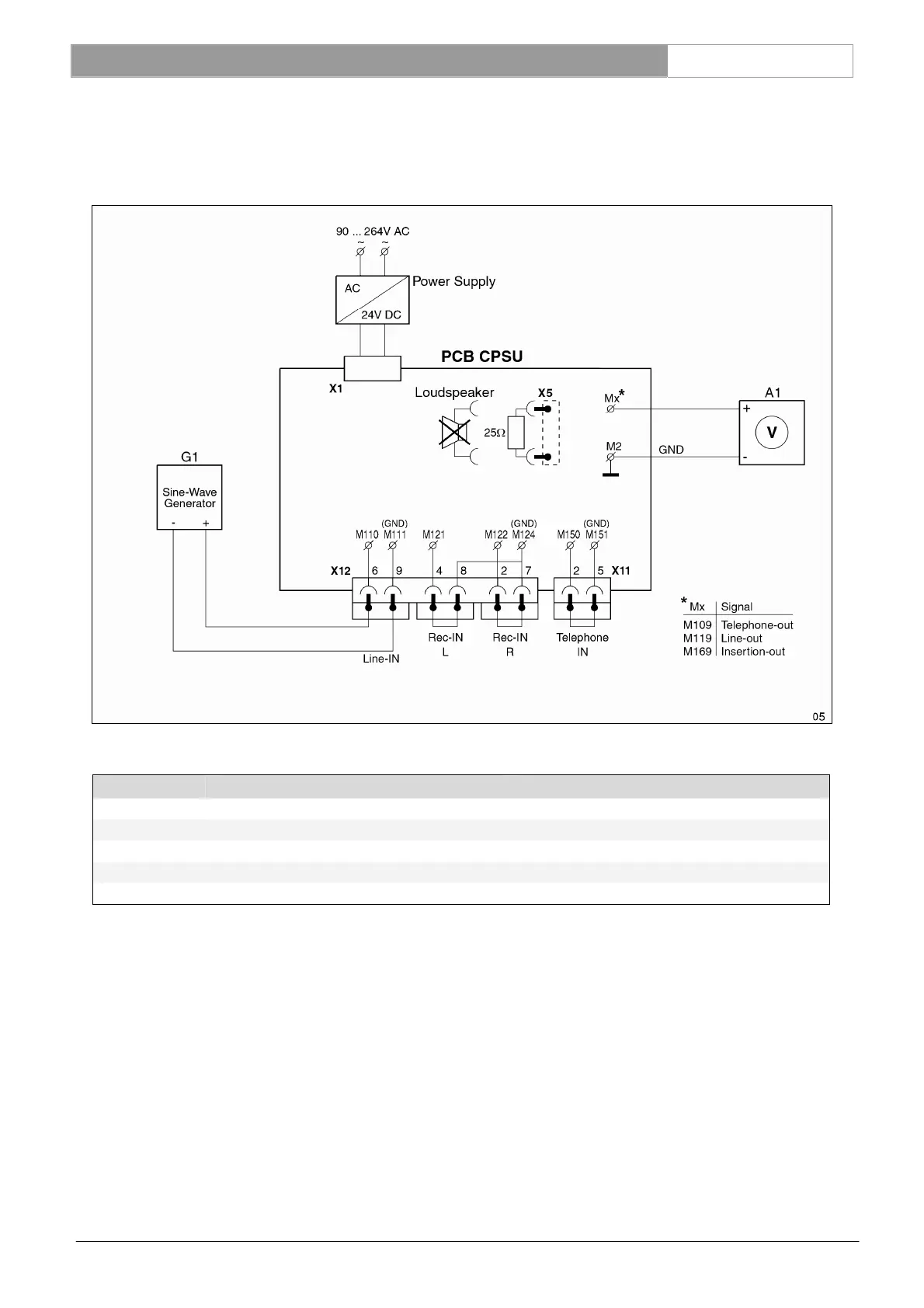
7.3.8 Telephone-out, Line-out and Insertion-out measurement
Connect a sine-wave generator to the LINE-IN connector and measure successively the output signal at the
TELEPHONE-OUT (M109), LINE-OUT (M119) and INSERTION-OUT“ (M169) connector.
Input setting G1: M110 related to M111 (GND), see table below.
Settings for G1 Measurement results for A1
Amplitude Frequency Amplification
Nominal level -14dBV (200mV
rms
) 1kHz -14dBV ± 1dB (85dB SPL)
Maximum level +11dBV (3.55V
rms
) 1 kHz +11dBV ± 1dB (110dB SPL)
Bandwidth -14dBV (200mV
rms
) 125 Hz -0.5dB ± 2dB related to nom. level at 1kHz
Bandwidth -14dBV (200mV
rms
) 12.5 kHz -1.0dB ± 1dB related to nom. level at 1kHz.
Reference: M169 See Ch. 13.5
M109, 119 See Ch. 13.6