CCS800 | Service manual | Chapter 7 | Diagnostics and faultfinding en | 23
Bosch Security Systems | 2005-01| 3922 880 21112
7.3.1 Settings before you start measuring
• Set the insertion switch (S1), located at the rear side, to the left position (“1”).
• Set the potentiometer of the headphone volume (R201) to maximum (fully clockwise).
• Set the mode switch (S2) to “auto mode 1” (fully counter clockwise).
• Set the Volume control (S3) for the Delegate and Chairman units to maximum (fully clockwise).
• Set the gain control potentiometer (R199) for the external microphone in the middle position.
• Set the gain control potentiometer (R200) for the recorder input in the middle position.
• Set AFS switch (S4) to Off (LBB 3310/10 only).
• Remove the loudspeaker connector (X3) and mount a 25 Ohm resistor on X5 pt. 2 and 4 (M57, M59). See illustration
chapter 13.3.1.
7.3.2 Internal Supply Voltages
Connect the CPSU to the mains and measure the following internal supply lines, related to M2 (= GND):
Measuring points on the bottom layout are colored in blue (See chapter 13.3).
Measuring points Measurement results
M6 (V+) +19.5 V ± 400 mV
M7 (V-) - 4.5 V ± 100 mV
M15 +15 V ± 750 mV
M25 +5 V ± 250 mV
M26 +7.5 V ± 350 mV
M27 +10 V ± 500 mV
7.3.3 Phantom supply of the external symmetrical microphone input
Measure the following internal supply lines, related to M133 (= GND):
Measuring points Measurement results
M28 +12 V ± 600 mV
M131 +12 V ± 600 mV
M132 +12 V ± 600 mV
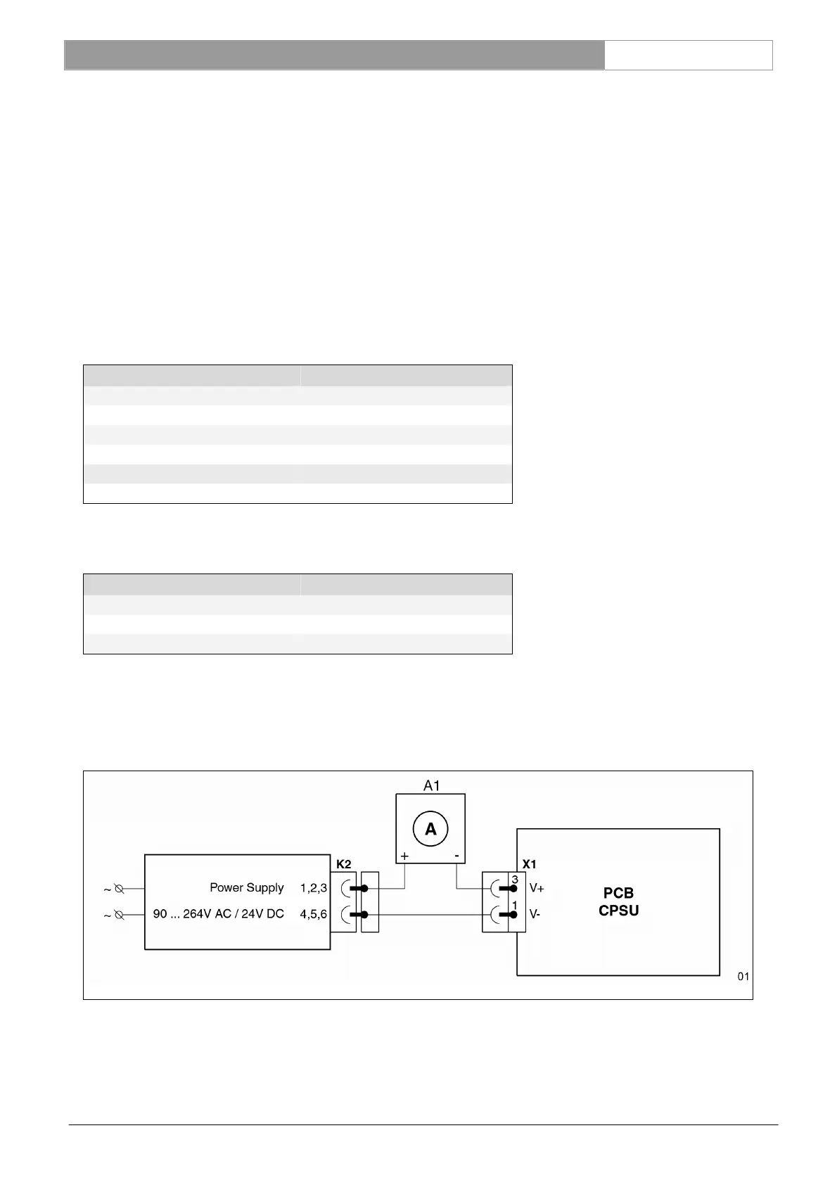
7.3.4 Supply current measurement.
Measure the supply current from V+ by means of a current meter in the power supply line itself: this should be between
30mA and 40mA.
On the CPSU board is the power supply voltage present after fuse F1 at measuring spot M9 (SUPP).
Reference: X1 See Ch. 13.7