CCS800 | Service manual | Chapter 7 | Diagnostics and faultfinding en | 34
Bosch Security Systems | 2005-01| 3922 880 21112
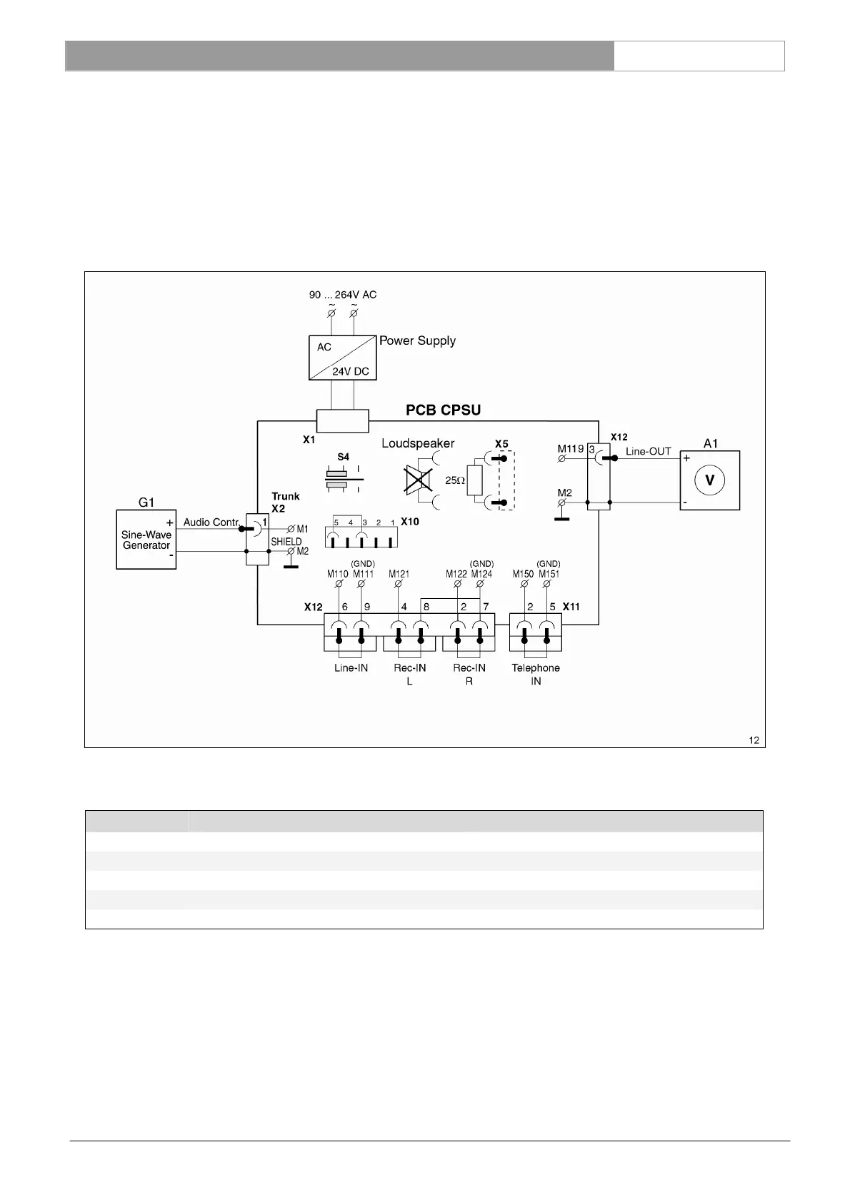
7.3.15 AUDIO CONTROL IN to LINE-OUT via AFS circuit of CPSU measurement
(LBB 3310/10 only)
Connect a sine-wave generator to one Trunk connectors (X2) M1 and measure the output signal at output LINE-OUT
(M119).
• Set AFS switch (S4) to position ‘On’.
• Connect on CPSU board X10-3 (audio out) to X10-5 (audio in). AFS board is not required for this test.
Input setting G1: X11 p-1 related to M2 (GND), see table below.
settings for G1 measurement results for A1
Amplitude Frequency Amplification
Nominal level -28dBV (39.8mV
rms
) 1 kHz -14dBV ± 2dB (85dB SPL)
Maximum level -3dBV (794mV
rms
) 1 kHz +11dBV ± 2dB (110dB SPL)
Bandwidth -28dBV (39.8mV
rms
) 125 Hz -0.5dB ± 1dB related to nom. level at 1kHz
Bandwidth -28dBV (39.8mV
rms
) 12.5 kHz -1dB ± 1dB related to nom. level at 1kHz.
• Set AFS switch (S4) to position ‘Off’.
Reference: X10, 12 See Ch. 13.6
X2 See Ch. 13.7