Flexible Automation
Subracks
2-9
1070 072 143-101
2.5 Expansion configuration
. The maximum address range of the control unit must always be ac
counted for when carrying out an expansion.
The expansion of a CL400 using the basic unit always begins with an Ex
pansion Module AG/PS in the basic unit.
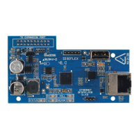
Expansion Module AG/PS
The Expansion Module AG/PS contains drivers which permit a maximum
connection cable to the Expansion Module AG/ZS of 1.8 m.
A maximum of 3 Expansion Modules AG/PS in may be operated in the
basic unit of the CL400.
. The Expansion Module AG/PS must not be plugged into the expansion
unit.
. More detailed information may be found in the manual:
Parallel Expansion Module AG/P
Module description
Ordering information
Description Order no.
Expansion Module AG/PS 1070 064 905
Connection Cable AG/PS (K14S) 1070 064 753
Parallel Expansion Module AG/P, Module description 1070 072 110
Fig. 2-8 Expansion Module AG/PS, ordering information
 Loading...


