D8125 | Installation and Operation Guide | 4.0 Installation
.
Bosch Security Systems B.V. | 2020.04 | F01U036298-15 11
4.2 9000 Series and G Series
Follow the procedure below to wire one or two D8125 POPEX modules to the 9000 Series, and G Series
control panels. For the B9512G, B9512G-E, B8512G, B8512G-E control panels, see the Control Panels
Installation and System Reference Guide.
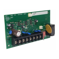
4.2.1 Wiring to the control panel
The B600 Retrofit (ZONEX) module is
required to use the D8125 on the
B9512G, B9512G-E, B8512G, and
B8512G-E control panels.
Remove all power (AC and Battery) before
making any connections. Failure to do so
may result in personal injury and/or
equipment damage.
4.2.2 Disconnecting the Battery and Transformer
1. Disconnect the battery by unhooking the positive (red) battery lead from the battery.
2. Unplug the transformer.
Reversed polarity damages the D8125.
Make sure you wire the D8125 AUX and
GND terminals to the control panel.
4.2.3 Wiring Procedure
For Points 9 up to Point 127:
1. Connect the GND terminal of the D8125 to the control panel ZONEX COMMON terminal.
2. Connect the OUT terminal of the D8125 POPEX module to ZONEX IN 1.
3. Connect the IN terminal of the D8125 POPEX module to ZONEX OUT 1.
4. Connect the AUX terminal of the D8125 to ZONEX POWER + terminal.
For Points 129 up to Point 247:
1. Connect the GND terminal of the D8125 to the control panel ZONEX COMMON terminal.
2. Connect the OUT terminal of the D8125 POPEX module to ZONEX IN 2.
3. Connect the IN terminal of the D8125 POPEX module to ZONEX OUT 2.
4. Connect the AUX terminal of the D8125 to ZONEX POWER + terminal.
Do not connect more than one D8125 to ZONEX 1 (IN and OUT terminals) or ZONEX 2 (IN and OUT terminals).

 Loading...