D8125 | Installation and Operation Guide | 4.0 Installation
Bosch Security Systems B.V. | 2020.04 |F01U036298-15
Step 5 is for POPEX #2 only.
5. Installing two POPEX Modules (in the horizontal or vertical mode): Repeat steps 1 through 3 for
POPEX #2; then connect D8112G terminal 27 to POPEX #2 OUT terminal.
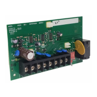
Before powering up the D8112, check
terminals 3 and 4 for correct wiring.
Reverse polarity WILL damage the POPEX
module.
6. Reconnect AC and DC power to the D811G1/G2.
4.3.2 POPIT Module Installation
4.3.2.1 Wiring POPITs to the Expansion Loop
The zone expansion loop is a two-conductor wire interconnecting all POPIT Modules assigned to a single
POPEX (see Figure 4). Up to three zone expansion loops can be connected to one D8125 when using
unshielded cable. The required wire gauge for the zone expansion loop(s) (up to three max.) can be
determined using Table 4. When using unshielded cable each zone expansion loop can be up to the distance
shown in Table 4.
Hint: AC induction or RF interference may occur when a ZONEX system is installed in or near the following:
• Radio station transmitter site or other broadcast station
• Ham radio transmitter site
• Computer network system
• Heavy machinery and motors
• PBX telephone system
• Welding shop
• High voltage electrical equipment or transformers
• Public service (police, fire department, etc.) using radio communications
• When wires must be run close to electrical lines, fluorescent fixtures or telephone cabling
POPIT Modules do not need to be wired in any particular order on the zone expansion loop. A switch setting
on each POPIT (see POPIT Module Assignments on page 19) identifies the point of protection, regardless of its
physical location.
The POPIT modules should be connected
to one another in parallel (see Figure 2).

 Loading...