D8125 | Installation and Operation Guide | 4.0 Installation
Bosch Security Systems B.V. | 2020.04 |F01U036298-15
4.2.4 Wiring POPITs to the Data Expansion Loop
Use one 2-wire data expansion loop or distribute the POPITs on up to three loops. Setting DIP switches on the
POPIT modules assigns them to point numbers. Refer to Section 4.2.6 POPIT Module Point Assignments.
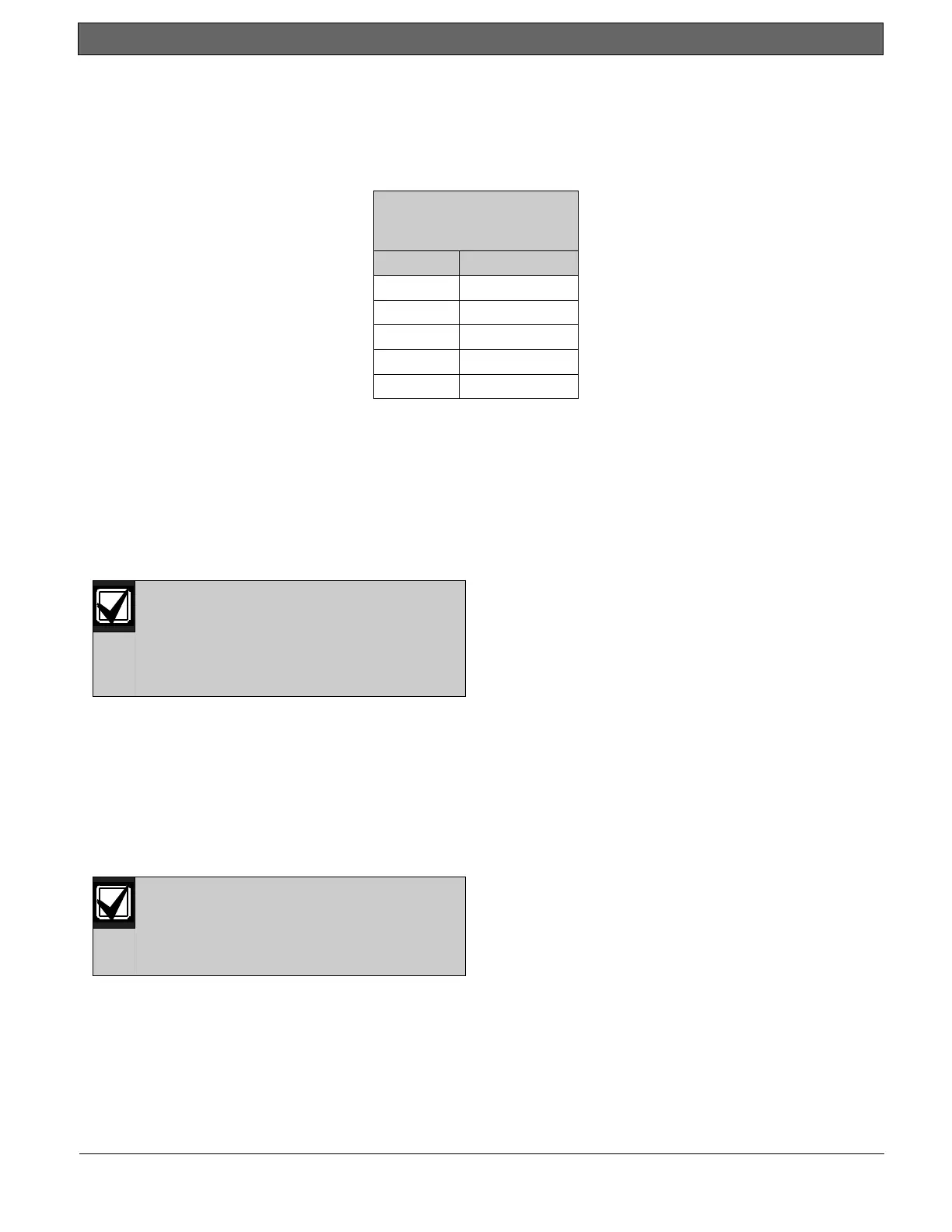
Determine the required wire gauge for each data expansion loop using Table 3.
Maximum Length of all
Data Expansion Loops
Combined
22 (0.8) 1800 (549)
20 (1.0) 2890 (881)
18 (1.2) 4600 (1402)
16 (1.5) 7320 (2231)
14 (1.8) 11650 (3551)
Table 3: Data Expansion Loop Wire Specifications
4.2.4.1 Combine data expansion loops
The maximum lengths shown in Table 3 are for all data expansion loops connected to the same POPEX module
combined.
Before installing the POPITs, make sure the resistance on the data expansion loop is no more than 40 Ω.
4.2.4.2 Wiring POPITs together
Do NOT connect POPITs to each other in
series, or with a T-tap. Doing so may
cause random missing POPIT conditions.
Follow the procedure below to connect
POPITs to one another in parallel. Figure
3 shows a typical configuration.
1. Connect the positive (+) Data terminal from one POPIT to the positive (+) Data terminal on the next
POPIT.
2. Connect the negative (-) Data terminal from one POPIT to the negative (-) Data terminal on the next
POPIT.
3. Repeat steps 1 and 2 to connect all POPITs to the expansion loop. You don’t need to wire the POPITs in
any particular order on the loop. The switch setting on each POPIT assigns it a point number, regardless
of its physical location.
Three inch clearance for tampered
POPITs: Mount tampered POPIT Modules
at least 3.0 in. (76 mm) apart to prevent
the tamper magnets from interfering with
each other.

 Loading...