D8125 | Installation and Operation Guide | 4.0 Installation
.
Bosch Security Systems B.V. | 2020.04 | F01U036298-15 15
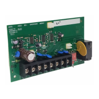
4.2.7 POPIT Module Point Assignments
D9127U/T POPITs have seven switches (0-6) that assign the module to a point number. Find POPIT switch
settings in the Point Assignment section of the Control Panel Program Record Sheet.
4.2.7.1 POPIT Labels
Two sheets of peel-off POPIT labels are supplied with the D8125 POPEX module. Use the sheet marked Bank1
for Points 9 to 127. Use the sheet marked Bank2 or Points 129 to 247.
Each label has two parts. Place the smaller part, with just the point number on it, on the chip. Place the larger
part with the switch settings on the base of the POPIT. Set the switches and cover the POPIT.
Do not program two POPITs for the same point number. After you program all the points, perform a service
walk test. The Troubleshooting section of this document contains instructions for performing a service walk
test. If a point does not test, check the programming for a duplicate address switch settings.
3.2.7.2 Three inch clearance for tampered POPITs
Mount tampered POPIT modules at least 3.0 in. (76 mm) apart to prevent the tamper magnets from interfering
with each other.
4.3 D8112G1/G2
4.3.1 Wiring to the control panel
Remove all power (AC and Battery) before
making any connections. Failure to do so
may result in personal injury and/or
equipment damage.
4.3.1.1 Disconnecting the Battery and Transformer
1. Disconnect the battery by unhooking the positive (red) battery lead from the battery.
2. Unplug the transformer.
Reversed polarity damages the D8125.
Make sure you correctly wire the D8125
AUX and GND terminals to the control
panel.
4.3.1.2 Wiring Procedure
1. Connect D8112G1/G2 Terminal 4 to the POPEX GND terminal (see Figure 4).
2. Connect D8112G1/G2 Terminal 3 to the POPEX AUX terminal.
3. Connect D8112G1/G2 Terminal 31 to the POPEX IN terminal.
4. Installing only one POPEX:
Horizontal Mode: Connect the POPEX OUT terminal to the D8112G1/G2 Terminal 28; then go to step
6.
Vertical Mode: Connect the POPEX OUT terminal to the D8112G1/G2 Terminal 27 or 28; then go to
step 6. If an Independent Zone Control (IZC) (D279 or D268/D269) is used, it is recommended that
the POPEX be connected to Terminal 27 on the D8112G2 and the IZC be attached to Zone 1, 2, 3, or 4.
This will allow you to maximize your COMEX ID Groups 6-8. For information concerning COMEX refer
to the COMEX Program Entry Guide (P/N: 74-05073-000).
Note: If the vertical mode is used, POPEX #2 can be installed without installing POPEX #1.

 Loading...