D8125 | Installation and Operation Guide | 3.0 Non-G 9000 Series Point Expansion
.
Bosch Security Systems B.V. | 2020.04 | F01U036298-15 9
3.3 D9124 Point Expansion
The D9124 Fire Alarm Control Panel (FACP) is currently shipped with the D9412GLTB control panel. Refer to
Section 2.0 9000 and G Series Point Expansion for details regarding POPIT installation.
You can connect up to four data expansion loops to one D8125 input at the motherboard. Data Loops 1 to 4
connect to the D8125 POPEX 1 input on the motherboard (Terminals 11 through 18). Data Loops 5 to 8
connect to the D8125 POPEX 2 input at the motherboard (Terminals 19 through 26).
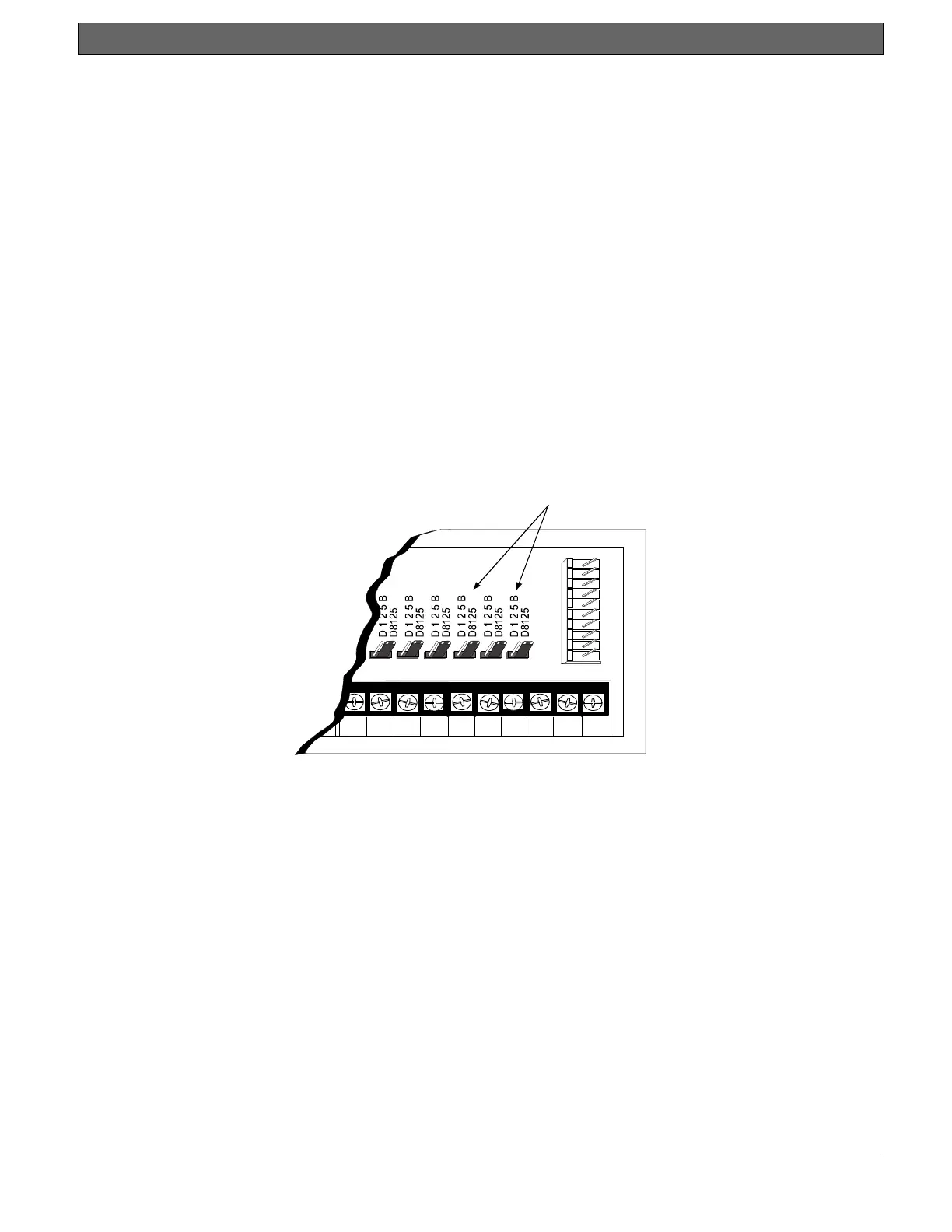
Verify the proper setting of motherboard jumpers: Make sure the jumpers above Terminals 18 to 24 on the
motherboard are in the D8125 position (Figure 1).
3.3.1 POPEX/POPIT Configurations
With the D8125 POPEX Module, you can use:
• D8125 POPEX 1, data loops 1 to 4 (Terminals 11 to 18) on the motherboard.
• install a maximum of 119 POPITs (Points 9 to 127).
• Points 7 and 8 for power supply and initiation circuit supervision. POPITs are not required for these
functions.
With an additional D8125 POPEX Module, you can:
• D8125 POPEX 2, data loops 5 to 8 (Terminals 19 to 26) on the motherboard.
• install an additional 119 POPITs (Points 129 to 247) for a maximum of 238 POPITs in the system.
J9
17 18 19 20 21 22 23 24 25 26
J9 J8 J7 J 1 2 J11 J 1 0
P5
Jumpers set in the
D8125 position.
Figure 1: D8125 Jumper Setting

 Loading...