D8125 | Installation and Operation Guide | 4.0 Installation
.
Bosch Security Systems B.V. | 2020.04 | F01U036298-15 23
Table 5 and Table 6 display all POPIT assignment switch settings for both the horizontal and vertical modes
(e.g., 1 2 3 4 - -). Numbers 1 through 6 indicate switches 1-6 on the POPIT Module. The dash (-) indicates a
switch is in the OFF or open position. These switches assign each point of protection to a master zone (refer to
Section 4.2.6 POPIT Module Point Assignments for switch settings). Table 5 and Table 6 indicate the maximum
number of POPITs that can be assigned to each D8112G1/G2 master zone, with one and two POPEX Modules.
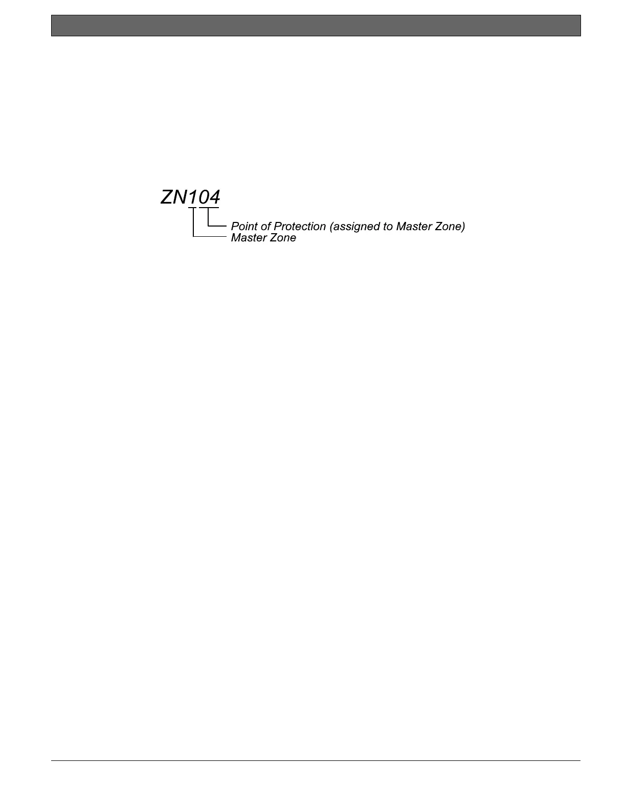
Below the switch setting is the I.D. code (e.g., ZN 104) for each POPIT. The master zone and expansion point
(point of protection) are used to cross-reference the POPIT Module to an event displayed on the D1252A
Keypad. For example, in the I.D. code ZN104, “ZN1” indicates that the POPIT is assigned to master zone 100 of
the D8112G1/G2 control panel, and “04” indicates that the POPIT reports as expansion point #4.

 Loading...