Aspirating Smoke Detector Planning | en 43
Bosch Sicherheitssysteme GmbH Operation Guide 2018.04 | 2.0 | F.01U.130.926
With detonation safety barrier
Number of air sampling openings
Pipe
shape
U
Fans
1 2 3 4 5 6 7 8 9 10 11 12 … 32
I 6.9 46 46 46 46 38 l [m]
≥9 68 68 68 68 68 68
U 6.9 60 60 60 60 60 60
≥9 60 60 60 60 60 60 60 60
M 6.9 80 80 80 80 80 80 70 70 70
≥9 120 120 120 120 120 120 120 120 120
2 x U 6.9 80 80 80 80 80 80 80 80
≥9 100 100 100 100 100 100 100 100
Results
The following modules can be used with the relevant settings for class B or A:
– 0.015% LT/m (0.05% LT/m) module – with a sensitivity of min. 0.12% LT/m (0.4% LT/m)
– 0.1% LT/m (0.25% LT/m) module – with a sensitivity of min. 0.2% LT/m (0.5% LT/m)
– 0.5% LT/m (0.8% LT/m) module – with setting 0.5% LT/m (0.8% LT/m)
System parameters possible:
– I-pipe system
9V fan voltage, max. 80m total pipe length for U-pipe system
– U-pipe system
6.9V fan voltage, max. 110m total pipe length
9V fan voltage, max. 110m total pipe length
– M-pipe system
6.9V fan voltage, max. 110m total pipe length
9V fan voltage, max. 160m total pipe length
– Double U-pipe system
6.9V fan voltage, max. 140m total pipe length
9V fan voltage, max. 160m total pipe length
Notice!
The sensitivity value is based on measurements with standard test fires (old value in
brackets).
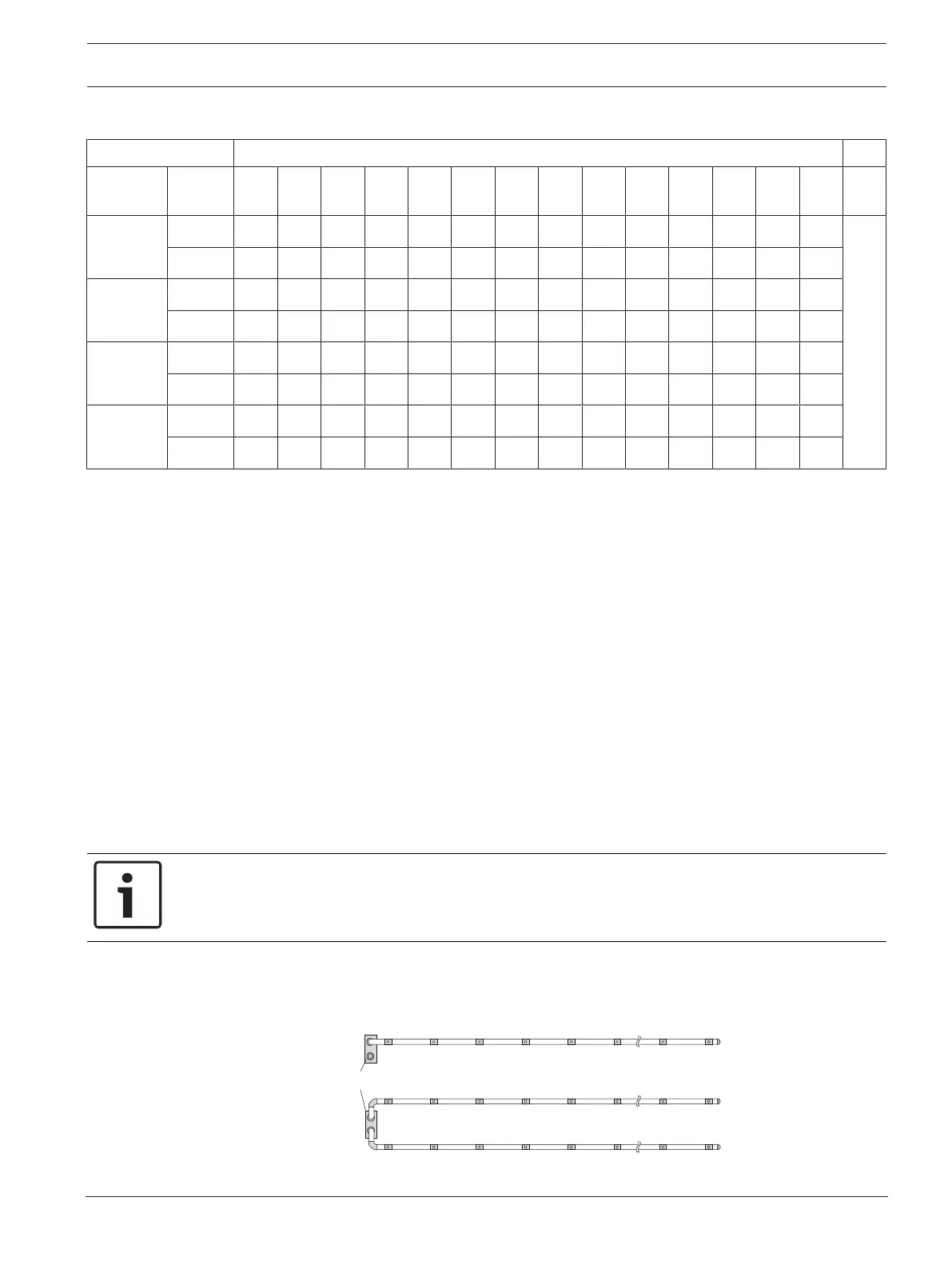
I-pipe system for space protection
The diameters of the air sampling openings should be taken from the relevant table for each
pipe configuration:
1 pipe system
FCS-320-TP1
FCS-320-TT1
2 pipe systems
FCS-320-TP2
FCS-320-TT2
FAS / FCS
A
B
C D E L MF
A
B
C D E L MF
I-pipe system for space protection