8 en | Introduction MAP 5000
2016.06 | 17 | F.01U.168.332 Installation manual Bosch Sicherheitssysteme GmbH
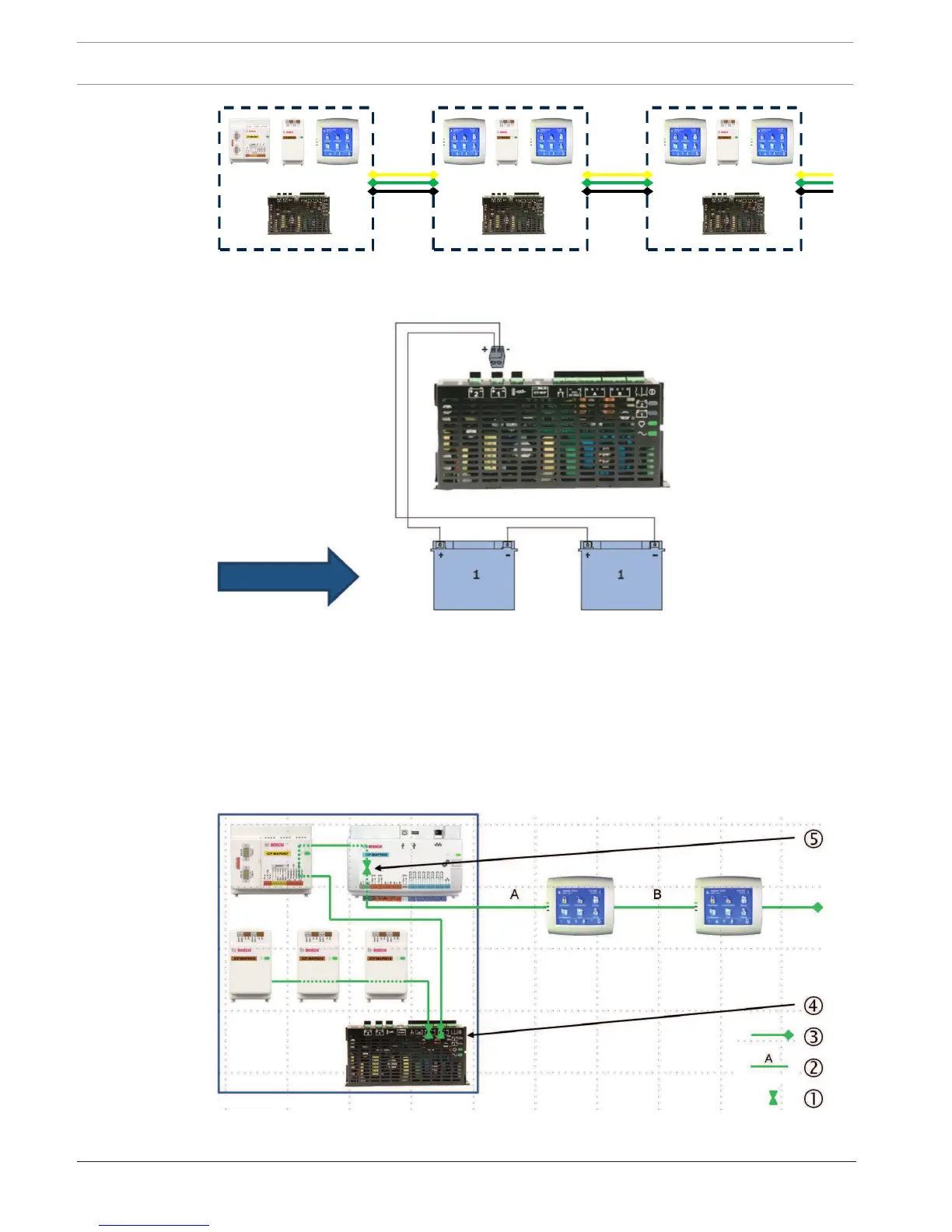
Figure1.1: Wiring of power supply segments
Condition 2
Charged batteries must be connected to the power supply to ensure reliable system start-up.
Figure1.2: Batteries for system booting
Condition 3
To ensure reliable system start-up, it is necessary to take into account the cable length and
wire gauge:
– between power supply and first control center
– between control centers
Refer to , page 10.
Typical configuration with ICP-MAP0111 panel enclosure
Main panel - DE module - 3 LSN gateway modules - max. 2 control centers