23
3. Description of Test Bench
The KPS 003 combination test bench consists of a generator
testing section, a starting motor testing section, indicator unit and
operating unit.
Fig. 1Fig. 1
Fig. 1Fig. 1
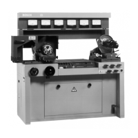
Fig. 1: Overall view
1 Operating panel for generator and starting-motor testing
2 Variable load resistor (generator testing)
3 Handwheel for height adjustment of clamping table, with stop (for
generators)
4 Generator test table with protective cowl
5 Socket for rotational speed sensor (generator testing)
6 Stacking plate
7 Indicators
8 Lighting console
9 Socket for rotational speed sensor (starting motor testing)
10 Starting motor test table
11 Terminals for starting motor
12 Battery compartment, lockable cover containing wiring and acces-
sories
13 Operating pedal for starting motor loading device (drum brake)
Fig. 2:Fig. 2:
Fig. 2:Fig. 2:
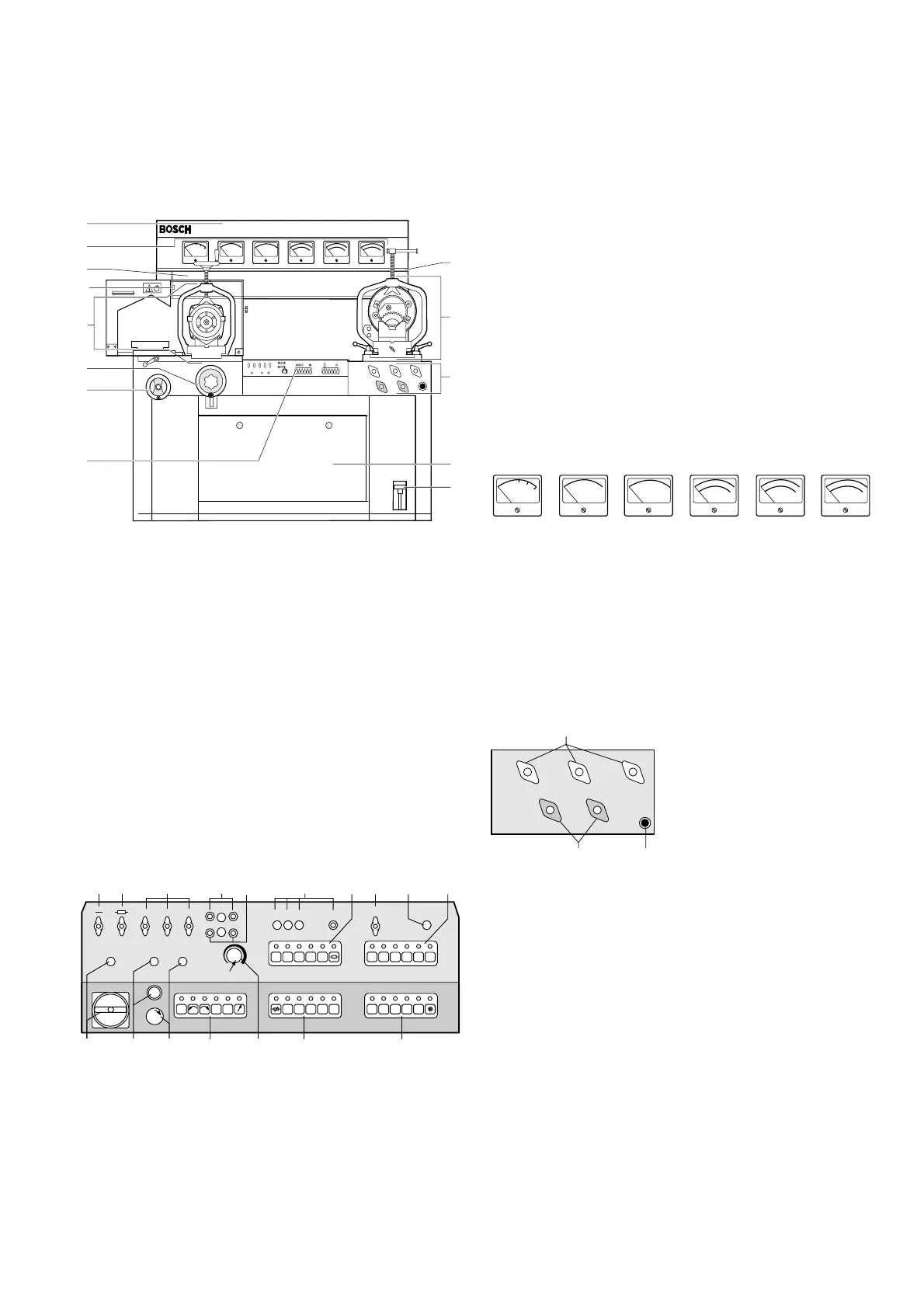
Fig. 2: Operating panel
20 Terminal to battery - (generator testing)
21 Terminal to the load resistor (generator testing)
22 Terminal to battery + (generator testing)
23 Connector bushings for ammeter 10A (generator testing)
24 Connector bushings for ammeter 10A (generator testing)
25 Charge indicator lamps with connector bushing D + / 61
(Generator testing)
26 Voltage selection key,
INT/EXTINT/EXT
INT/EXTINT/EXT
INT/EXT key, back-up resistance
(generator testing)
27 Terminal for terminal 50 for actuating the engagement switch on
starting motors (starting motor testing)
28
AKKU MINUSAKKU MINUS
AKKU MINUSAKKU MINUS
AKKU MINUS indicator lamp
29 Voltage selection key, current selection (starting motor testing)
AKKU MINUSAKKU MINUS
AKKU MINUSAKKU MINUS
AKKU MINUS key (starting motor and generator testing)
30
Key (6000/12000 rpm) for rotational speed selection (generator and
starting motor testing)
Key (60/120 A) measuring-range selection generator testing
LampLamp
LampLamp
Lamp
key for lighting
31 Key for load resistances (generator testing)
32 Drive motor rotational speed adjustment (generator testing)
33 Key for selecting direction and speed of rotation, drive motor
(generator testing)
34
EMERGENCYEMERGENCY
EMERGENCYEMERGENCY
EMERGENCY push-button = drive
OffOff
OffOff
Off and indicator lamp
OnOn
OnOn
On
(generator testing)
35
MOTORMOTOR
MOTORMOTOR
MOTOR push-button and indicator lamp (generator testing)
36 Main switch =
EMERGENCY-OFFEMERGENCY-OFF
EMERGENCY-OFFEMERGENCY-OFF
EMERGENCY-OFF function and indicator lamp
Fig. 3Fig. 3
Fig. 3Fig. 3
Fig. 3: Display instrument unit
40 Rotational speed 6000 rpm
41 Ammeter 60/120 A
42 Ammeter 10 A
43 Voltmeter 0-10/20/40 V
44 Rotational speed 6000/12000 rpm
45 Ammeter 300/1800 A
Fig. 4Fig. 4
Fig. 4Fig. 4
Fig. 4: Starting motor terminals
50 Terminals for starting motor plus wire 6/12/24 V
51 Starting-motor push-button
52 Terminals for starting motor minus wire
- connect small starting motor to -300 A terminal
- connect large starting motor to -1800 A terminal
458712P
120
60
A
41
V
43
min
x100
44
10
A
42
1800
300
A
45
-1
40
min
x100
-1
458468P
50
52
+6V
+12V
+24V
-300A
-1800A
51
9
11
13
8
7
6
5
4
3
2
1
12
458470P
10
120
60
A
41
V
43
min
x100
44
10
A
42
1800
300
A
45
-1
40
min
x100
-1
7 14 28 INT. EXT.
458473P
START
6V 12V 24V
300
AKKU
MINUS
123 5
RUN 1500 3000
4
RPM.
30
27
25
23
2221
20
24
RPM.
35 34
32
+6V +12V +24V
10A
A
V
+
_
6V 12V 24V D+/61
AKKU
MINUS
50
WARNING
ON/OFF
MOTOR
EMERGENCY
2826
29
31
36
33
1800
60
120
6000
12000