32
7.3 Electrical connection
i The ground cable fitted to the generator clamping device
must be disconnected; otherwise false measurements are
possible.
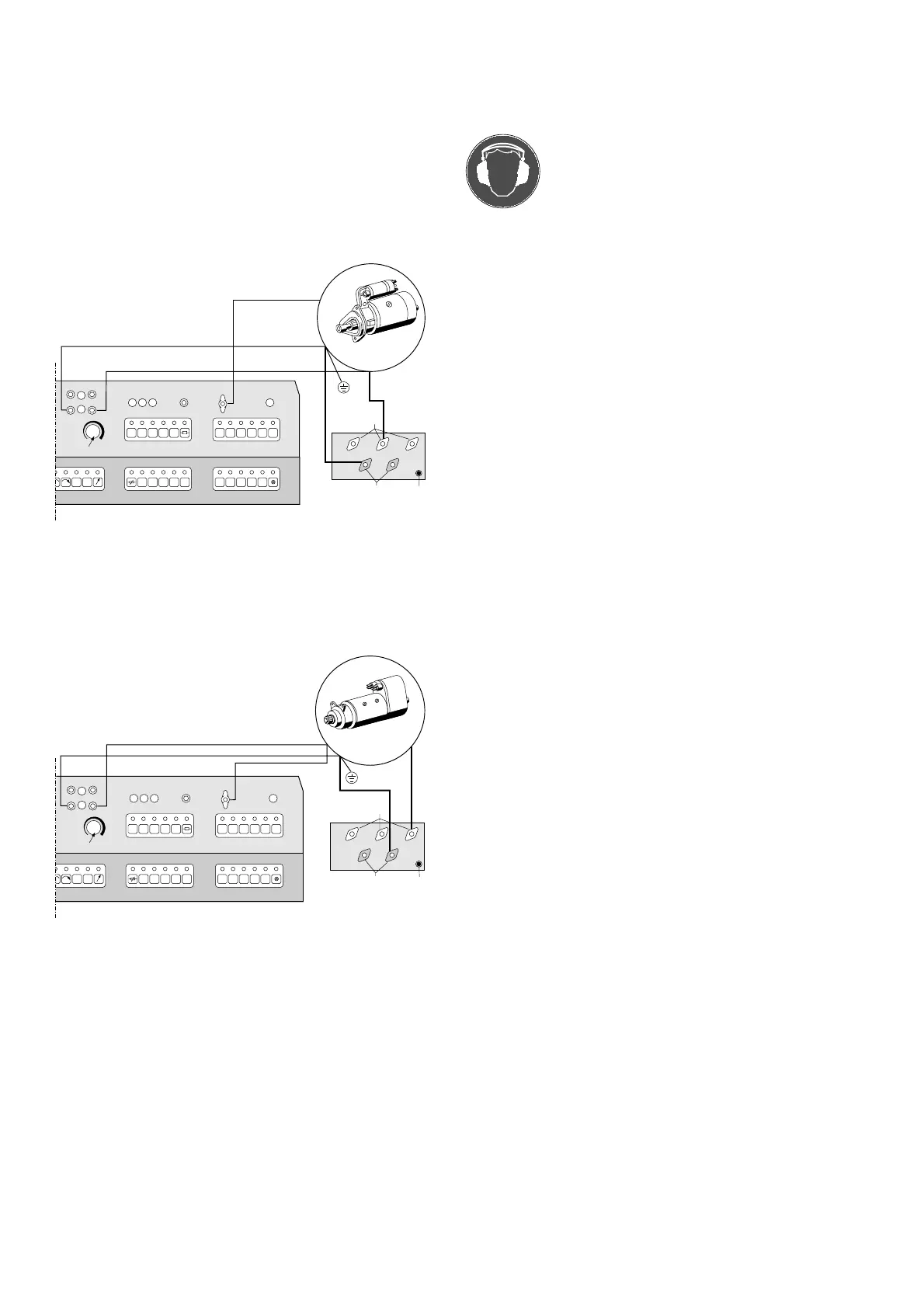
7.3.1 Shunt-screw drive starting motor
Fig. 18Fig. 18
Fig. 18Fig. 18
Fig. 18: Connecting diagram shunt-screw drive starting motor
Measuring and control cables (thin lines)
Power cables (thick lines)
7.3.2 Screw drive starting motor
Fig. 19Fig. 19
Fig. 19Fig. 19
Fig. 19: Connecting diagram screw drive starting motor
Measuring and control cables (thin lines)
Power cables (thick lines)
i Starting motors with + to ground are to be connected in the
same basic manner.
7.4 Testing starting motors
Operators must wear ear protectors during
testing.
7.4.1 Load test
Is sufficient as a functional test (without test values) reveals:
- Out-of-round collectors
- Worn-out bushings
- Inter-turn short-circuit in armature or excitation winding
- Armature open-circuit
- Close the protective cover over the ring gear.
- Switch on main switch (36).
Indicator lamp (36) lights up.
- Select the key 6, 12 or 24 (29) in accordance with the starting
motor (6 V, 12 V or 24 V).
LED lights up.
- Adjust current measuring range with key 300 / 1800 (29).
LED lights up.
Ammeter (45) set to current range 300 A.
LED off.
Ammeter (45) set to current range 1800 A.
- Set test speed with key 6000 / 12000 (30).
LED lights up.
Rotational speed display (44) set to test speed 6000 rpm.
LED off.
Rotational speed display (44) set to test speed 12000 rpm.
- Make battery connection by pressing the key AKKU MINUS (29).
LED lights up!
Indicator lamp (28) lights up.
- Press START key (29).
LED lights up.
- and press starting motor test key (51) simultaneously.
Starting motor is running.
i Two-handed operation!
The keys START and starting motor test must be
pressed simultaneously to start the starting motor.
- Actuate brake pedal (13).
- Apply load to starting motor in accordance with characteristic
data.
7 14 28 INT. EXT.
START
6V 12V 24V
300
AKKU
MINUS
123 5
1500 3000
4
RPM.
RPM.
10A
A
V
+
_
6V 12V 24V D+/61
AKKU
MINUS
50
1800
60
120
6000
12000
30
50
+6V
+12V
+24V
-300A
-1800A
50
52
458473/7P
51
7 14 28 INT. EXT.
START
6V 12V 24V
300
AKKU
MINUS
123 5
1500 3000
4
RPM.
RPM.
10A
A
V
+
_
6V 12V 24V D+/61
AKKU
MINUS
50
1800
60
120
6000
12000
30a
31
50
50
52
+6V
+12V
+24V
-300A
-1800A
458473/8P
51