6 720 800 095 (2014/05)Therm 6000S
Regulation | 9
2.10 Operational instructions
Hot water
Open the gas and water valves and ensure that all joints are
hermetic.
Place the principle switch (Fig. 4, [1]) in the operating position
(chapter 4.3), so that the appliance is quickly ready for use.
When a hot tap is opened, the water ow sensor should be in
(Fig. 2, [2]) send a signal to the control unit. This signal
initiates the following:
• The fan starts working
• Simultaneously, sparks are produced and the gas valve
opens.
• The burner lights.
• The ionisation electrode controls the state of the ame.
• The water temperature is controlled automatically by the
sensors/controllers according to the temperature selected.
Security cut-o when safety period is surpassed
If a ame is not achieved within the stipulated security period
(35 sec), a security cut-o will occur.
The presence of air in the gas inlet pipe (when the appliance is
used after long periods of inactivity for example) may delay
ignition.
In this case, if the attempts to ignite go on too long, the security
mechanisms prevent operation.
Security cut-o due to excessive water heating
The control unit detects the heating temperature via a NTC
resistor located in the hot water exit tube and the temperature
limiter located in the heat exchanger. If it detects an excessive
temperature it provokes a security cut-o.
Restarting after security cut-o
To restart the appliance following a security cut-o:
Press the reset key (Fig. 19).
3 Regulation
Any local by-laws and regulations pertaining to installation and
use of gas-heated appliances must be observed. Please refer to
the laws that should be attended in your country.
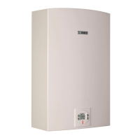
4 Operating instructions
Fig. 4
[1] Main switch ON/OFF
[2] Reset key
[3] Program key
[4] LCD panel
[5] Temperature increase key/ programming key
[6] Temperature decrease key / programming key
[7] LED
The installation may only be carried out by
registered installers and shall comply with
the requirements of SANS 10087-1.
 Loading...