User manual WTS Ver.1.16
Seite 28 von 52
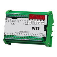
All analog outputs of the instrument are ACTIVE and SINGLE ENDED type,
therefore they can be connected only to PASSIVE receiver devices. The minimum
load allowed for voltage outputs is 10 kohm, the maximum load allowed for current
outputs is 300 ohm.
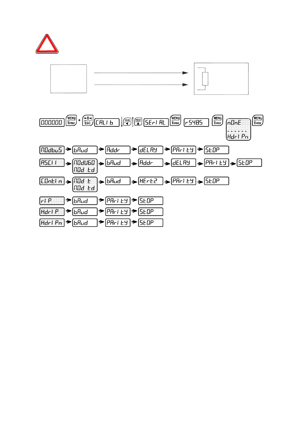
9.12 SERIAL COMMUNICATION SETTING
According to the chosen protocol only the necessary settings will be displayed in
sequence (see diagram here above).
-
: communication port.
-
: it disables any type of communication (default).
-
: MODBUS-RTU protocol; possible addresses: from 1 to 99 (see
Communication Protocols).
-
: ASCII bidirectional protocol; possible addresses: from 1 to 99 (see
Communication Protocols).
-
-
-
: continuous weight transmission protocol (see Communication protocols
manual), at the frequency set in
item (from 10 to 80).
-
(set:
=
,
=
).
-
(set:
=
,
=
).
-
: continuous weight transmission protocol to RIP5/20/60, RIP50SHA, RIPLED
series remote displays; the remote display shows the net weight or gross weight
according to its settings (set:
=
,
=
,
=
).
ACTIVE
ANALOG
OUTPUT
PASSIVE
RECEIVER
Voltage or current analog signal
- COMMON